A bundle connection point is used to specify the position and the direction of the bundle segment connected to the device.
-
Click Define Bundle Connection Point
 .
. -
Select the electrical device where you want the bundle connection point to be defined.
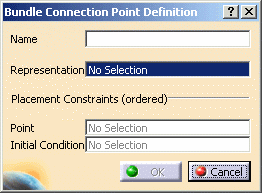
The Bundle Connection Point Definition dialog box opens: 
-
Enter a value in the Name field.
-
Select a Representation, for example a surface or a point...
-
Set a Point constraint: select a point.
This point will possibly be used as bundle segment extremity. -
Set an Initial Condition constraint: select a plane or an axis.
This plane or axis will possibly be used to orientate the bundle segment. -
Click OK to validate.
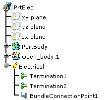
The specification tree is updated. 
You can add bundle connection points to:
- Equipment
- Mounting equipment
- Connector shells
- Single insert connectors, studs, external splices, terminal strips, terminal blocks
- Contacts
- Back shells.