Refer to Defining an Equipment.
-
Click Define Connector
 .
.
You are prompted to select a part or a product. -
Select ConnectorStd either in the specification tree or in the geometry area.
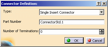
The Connector Definition dialog box opens: 
-
Select the desired Type of connector using the combo:

The different types available are: - Single Insert Connector: male or female connector
- Stud: connector used to secure bundle segments
- External Splice: connector used to secure bundle segments from different geometrical bundles
- Terminal Strip: connector with electrical termination strips
- Terminal Block: connector used to secure bundle segments, each bundle segment wire being connected to a termination
- Multi Insert Connector: connector mounting single insert connectors
- Internal Splice:
connector used between wires belonging to the same bundle segment.

An internal splice is a CATProduct document with no associated geometry. It is only available in the context of Electrical Assembly Design workbench but not in Electrical Part Design workbench. If you opened the sample document, this connector type is not proposed in the Type list because all products in the sample document have associated geometry.
-
Enter ConnectorElec in the Part Number field.
-
Enter the Number of Terminations to be defined onto the connector.
The electrical terminations are used to connect wires, using CATIA - Electrical Wire Routing. -
Click OK to validate.
The specification tree is updated.
The selected object is now an electrical connector as the electrical behavior has been added.

A single insert connector allows one cavity connection point, one connector connection point, one back shell connection point, bundle connection points, terminations and cavities.
You can connect one single insert connector to each connector connection point and plug this connector into mounting equipment via the cavity connection point.
Note: Since signal routing is not supported, wire routing is recommended. The electrical connection is not established between two connector connection points inside this type of connector.