![]()
This task shows how to create a connection between a bundle segment and a device or between two bundle segments.
![]()
This applies to multi-branchable and single bundle
segments.
You can also link a single bundle segment to a branch.
![]()
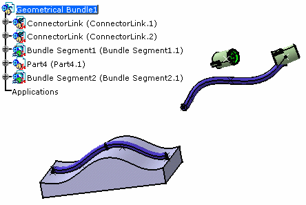
Open the Link.CATProduct document.
Note: if the Geometrical link option is not activated, only the electrical link is created.
-
You are prompted to select the bundle segment you want to connect. 
- CATIA finds the closest bundle segment extremity according to the selection point.
-
-
Select Bundle Segment1 close to the extremity to be connected.

>> The extremity is highlighted:

You are prompted to select another bundle segment extremity or a device. -
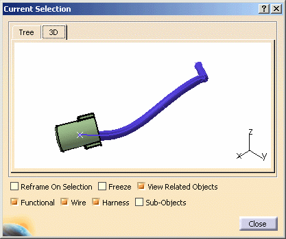
Select ConnectorLink2.

>> The connector is highlighted indicating that the selection is allowed: the connector includes a bundle connection point.  CATIA
finds the closest bundle connection point according to the
selection point.
CATIA
finds the closest bundle connection point according to the
selection point.A message is displayed asking you to confirm the selection. -
When you are satisfied, click OK validate your choice.
The bundle segment is computed.
The result looks like this: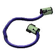
Note that you can add or reverse tangent.
Linking Bundle Segments Following a Part
![]()
-
Click Link
 .
.You are prompted to select the bundle segment you want to connect. 
You must choose first the bundle segment which is not following the part.
Otherwise the construction is not possible. -
Select Bundle Segment1 close to the extremity to be connected.

>> The extremity is highlighted:

You are prompted to select another bundle segment extremity or a device. -
Select Bundle Segment2 close to the extremity to be connected.
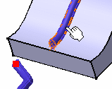
>> 
CATIA generates the point for the connection A message is displayed asking you to confirm the selection.
-
Click OK validate your choice.
The bundle segment is computed.
The result looks like this: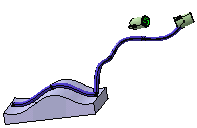
As you see, there is no tangency applied to the bundle segments.
You can modify the route and define a tangent. -
Double-click to edit the bundle segment newly routed.
The Bundle Segment Definition dialog box opens. -
Click Route Definition.
The Bundle Segment Route Definition window opens. -
Click More>>. It shows like this:
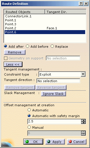
Note that the bundle segment extremity (Point.6) is selected. -
Click the Tangent direction field and select the bundle segment flexible curve as shown below:
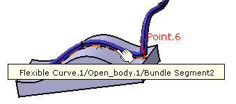
The dialog box is updated: 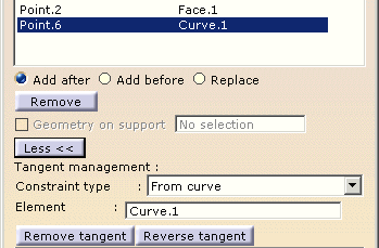
as well as the geometry: 
-
