- This functionality applies to multi-branchable documents only.
- This command cannot be used for retainers and adaptive supports since bundle segments are automatically positioned in these supports and cannot be re-arranged.
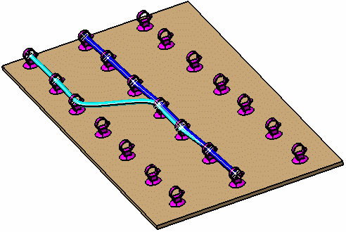
-
Click Arrange Bundle Segments
 .
.Note: Rotating a support along the support axis does not affect the bundle arrangement. This means, however, that some bundle segments may be positioned outside the rotated support. If this occurs, you can re-arrange segments manually or, propagate the arrangement of an un-rotated support.
A message appears to this effect when you select this command. Click OK to continue.You are prompted to select a support.
-
Select a support.
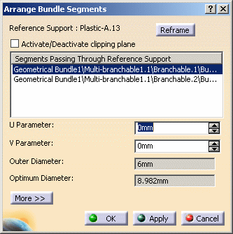
The selected bundle segment is highlighted in the geometry area. The Arrange Bundle Segments dialog box appears. Bundle segments routed through the selected support are listed.

-
Click Reframe to center the 3D view on the selected support and set the support parallel to the screen.
-
Select the Activate/Deactivate clipping plane check box to better visualize the selected support.
U and V axes are displayed in the geometry area. The origin of the 2D U,V axis system is positioned on the center of the support. The outer and optimum diameters are also displayed. 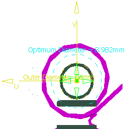

Outer and Optimum Diameters
The outer and optimum diameters are displayed to help you.
- The Outer diameter of all bundle segments routed
through the support.
It is computed as follows:Outer diameter = 2*Max (distance (O, Oi) + Ri)
where:
O is the center of the support
Oi is the center of bundle segment i
Ri is the radius of bundle segment i
The outer diameter represents the smallest circle whose center is O that contains all bundle segments routed through the selected support.
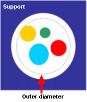
This value is updated each time the U,V parameters are changed. - The Optimal diameter is computed as follows:
Optimal diameter = 1.15*sqrt (sum of ((segment_radius'*2)**2))
This value takes into account the deformation of bundle segments when tied together in a support.
Note that protective coverings are not taken into account for computed diameters.
- The Outer diameter of all bundle segments routed
through the support.
-
In the geometry area, move the bundle segment to the desired location inside the support.
Use the green tool to assist you move the bundle segment to the desired location along U and V axes. This tool is positioned on the center of the bundle segment. U, V parameters give the distance of the bundle segment from the center of the support. 
U,V parameters in the dialog box are updated accordingly. 
You can also arrange the bundle segment inside the support by modifying the U,V parameters directly in the dialog box. -
Select another bundle segment in the list and adjust to desired location inside the support.
The entire bundle segment is highlighted in the geometry area. -
Repeat as necessary to arrange all bundle segments routed through the selected support.
-
Click More>> to expand the dialog box.
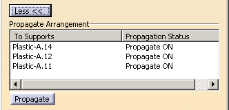
Important: The bundle segment arrangement can only be propagated to other supports in the route provided they contain the same bundle segments and are of the same type (i.e. same part number). Supports meeting these conditions are listed in the dialog box. They are also identified by a Propagate ON label in the geometry area. You can choose to individually propagate the arrangement to some of these supports.
-
Propagate ON (green 3D label) identifies supports that can be re-arranged.
Double-clicking the text toggles the label to Propagate OFF; the support will retain the previous arrangement.
- Propagate OFF (red 3D label) identifies supports that cannot be re-arranged.
A contextual menu in the Propagate Arrangement list also lets you toggle the status from ON to OFF and vice-versa.
-
-
Optionally, select Propagate to keep the same bundle segment arrangement in all selected supports in the route.
-
Click OK when done.