Routing branches along external curves allows you to use more elaborated geometry than the electrical flexible curve. The external curve can be created inside or outside the CATPart document.
![]()
You cannot route single bundle segments along external
curve using this scenario.
Refer to Routing single bundle segments along
external curves.
Valid external curves are curves of the following types: spline, line, helix, spiral, split, join, projection, intersection, corner and connected.
- Bundle segment geometry is created with the selected curve as center curve.
- You can add branch points anywhere along the curve.
- Some parameters are unavailable:
- Bend radius
- Build mode (slack, length, bend)
Since the branch center curve is a predefined curve, these parameters are no longer pertinent.
- Only Diameter and Section are available.
- To modify the bundle segment shape, you must edit/modify the selected curve.
- Since the branch is built on an external curve, you cannot add definition points, vectors, or devices to the spine definition.
- A branch is created for each external curve: It is not possible to select more than one external curve at a time for each branch, but it is possible to use joins and other types of curves combining several curves.
- Electrical connections are automatically created if the ends of the external curve correspond to bundle segment extremities.
- Electrical connections are created only in the branch definition
command.
If the ends of the external curve are modified, no electrical connection update is done. - The branch length is the external curve length.
-
Double-click to activate the root product: GeometricalBundle1
-
Click Multi-Branchable Document
 .
.The Electrical Harness Assembly workbench switches to the Electrical Harness Installation workbench. The Branch Definition dialog box opens: 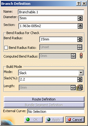
-
Click the External Curve box and select the curve in the geometry (Part.1):

Reminder: if you are working in Visualization mode, double-click Part.1 to display the curve. 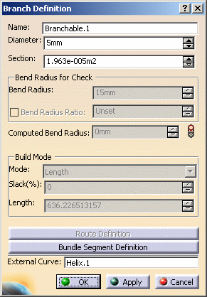
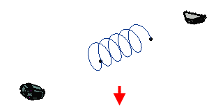
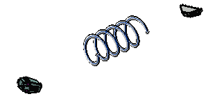
When selecting the external curve in the geometry: - OK and Apply become available
- The shape is automatically generated
- Route Definition is unavailable: no modification to the external curve route can be made
- Bend Radius and Build Mode are unavailable
- The length of the branch is displayed in the Length box: this is the length of the external curve.
-
Optional, to modify the external curve:
- Reset the External Curve field with the contextual
menu

- Select another external curve in the geometry
- Or, directly edit the external curve.
- Reset the External Curve field with the contextual
menu
-
Click OK when done.
-
Add other branches to join the branch you just defined to connectors.
-
Click Branch Definition
 .
.
The dialog box opens. Fill up the parameters of interest. -
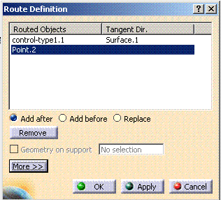
Click Route Definition and select the objects of interest to define the route of the branch.
-
Click OK to validate.
-
Repeat these steps for the other extremity.
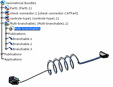
The final result looks like this:
-