- The ElectricalFlattening.CATProduct is still open from the previous task.
- Set the default roll radius in the Flattening Parameters dialog box.
-
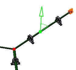
Select a point along the bundle segment you want to roll.
A green square and arrow appear identifying the point selected.
The branch end closest to the point of selection is taken as the reference point and is highlighted by a red square. The distance between this first roll point and the reference point is given in the dialog box (Position).

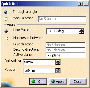
A dialog box also appears:

-
Optional, adjust the position of the roll point in the dialog box.
-
Optional, adjust the roll radius.
The default value in the dialog box is that specified via the default roll radius option in the Flattening Parameters dialog box. Note: The value entered can be less than the minimum bend radius.
-
Define the roll.
You can define the roll by specifying:-
The main direction.
You can select a line, an edge or another bundle segment as the roll direction. -
Or, an angle:
Either directly in the User value box,
Or,
By selecting two directions to retrieve the angle value.As above, you can select a line or an edge. Once the two directions have been defined, the angle between them is automatically calculated.
Note: By default, the roll plane is the active plane defined in the Flattening Parameters at the beginning of your session.
-
-
Click Apply. Entered values are applied but the dialog box remains open and you can still modify the inputs.
-
Click OK to validate.
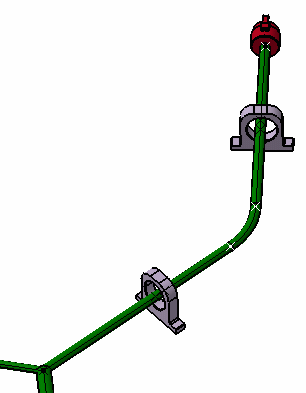
The result looks like this. 
- Multi-profile bundle segments: in order to avoid twisted and impossible configurations, the local V-axis of the profile sketch is kept aligned with the normal direction of the active plane.
- Mechanical parts: a dashed green line visualizes the link between the bundle segment and mechanical part. Use the compass to reposition the part properly.