This task shows you how to turn a part of a bundle segment about an intermediate point to give it a new direction. Bending lets you twist the bundle segment out of the active plane of the flattened harness.
-
Select the bundle segment or branch you want to bend.
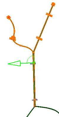
The intermediate point closest to the point of selection is selected as the bend point. It is highlighted as a green square in the geometry area. The intermediate point can be a constraint point or a branch point.
Make your selection in the geometry area and not in the specification tree, since the exact position of the intermediate point has to be known.
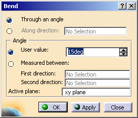
The Bend dialog box pops up.

A green arrow indicating the bundle direction appears in the geometry area and all impacted bundle segments are highlighted letting you check the impact of your action.
You can also click the green arrow and arc of circle to change the direction the bundle segment will take.

-
Define the bend by specifying:
-
A main direction.
You can select an edge, line, or another bundle segment.
Or,
-
An angle.
If you specify an angle, you can enter a value or select two directions to retrieve the angle between selected directions.
-
-
Click OK to validate.
-
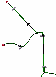
The result looks like this.

- When bending bundle segments in a closed harness loop, the loop is automatically opened at the free end of the selected bundle segment and a green line created to serve as a reminder that a link exists.
- Multi-profile bundle segments: in order to avoid twisted and impossible configurations, the local V-axis of the profile sketch is kept aligned with the normal direction of the active plane.
- Mechanical parts: a dashed green line visualizes the link between the bundle segment and mechanical part. Use the compass to reposition the part properly.