![]()
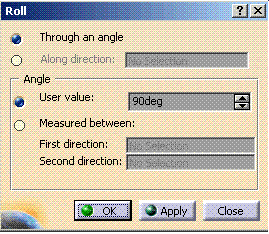
This task shows you how to turn a bundle segment within the plane of the flattened harness about a virtual point.
The ElectricalFlattening.CATProduct is still open and the harness has been flattened.
-
You are prompted to select a bundle segment or a 3D point. The Roll dialog box appears.

The geometrical bundle is automatically viewed in the active plane you defined in the Harness Flattening Parameters dialog box at the beginning of your session, and the active plane is set parallel to the screen.
Note that to roll a bundle segment created along an external curve, you must flatten the bundle segment first.
-
Select a 2D point in the geometry area.
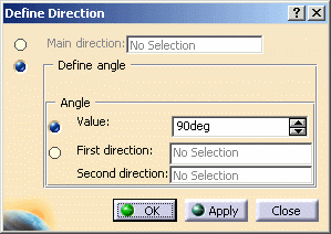
The Define Direction dialog box opens.

In a similar way to the previous task, you can define the roll by specifying:
-
A main direction
-
An angle.
If you specify an angle, you can enter a value or select two directions to retrieve the angle between selected directions.
Note: The Plane field is no longer visible in the dialog box, since the geometrical bundle automatically switches position to the right plane.
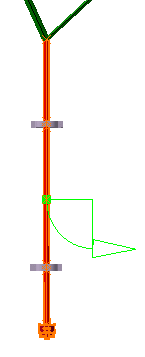
All bundle segments impacted by the roll are highlighted in the geometry area, letting you check the impact of your action.
A green arrow and an arc of circle appear in the geometry area. They indicate the virtual point around which the bundle segment is about to turn and the curve the bundle segment is about to follow. The user can modify the angle by selecting the green arrow directly.

-
-
Click OK to validate.
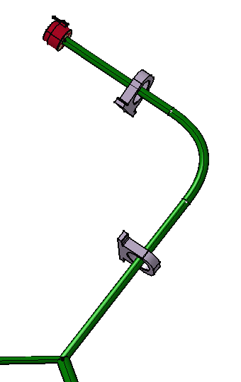
The result looks like this.

Note: Two new points have been added. They are shown in white in the geometry area and they indicate the tangent lines the bundle segment follows.
Two different cases can be considered:
- The bundle segment is long enough to roll entirely around the virtual point.
- The bundle segment is too short and it winds round the point, following the curve to a certain extent without being completely rolled.
- When rolling bundle segments in a closed harness loop, the loop is automatically opened at the free end of the selected bundle segment and a green line created to serve as a reminder that a link exists.
- Multi-profile bundle segments: in order to avoid twisted and impossible configurations, the local V-axis of the profile sketch is kept aligned with the normal direction of the active plane.
- Mechanical parts: a dashed green line visualizes the link between the bundle segment and mechanical part. Use the compass to reposition the part properly.