Importing Systems & Inter-System Connections
from Other Applications
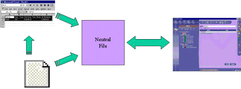
You can import
systems from other applications via a neutral file into Electrical System
Functional Definition. Connections between the system you want to import and
other systems are also managed.
Neutral files can be written directly, or you
can also use other applications, for example an Excel spreadsheet, to generate
data which you then save in neutral file format.

 |
This task explains how to import systems into the Electrical System
Functional Definition application.
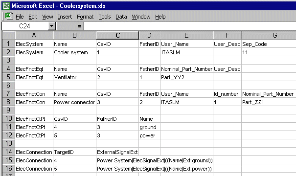
In this example, you will import a system from an Excel file. The import
will be done in two steps:
- Preparing the Excel file and saving it in the CSV (comma delimited)
format
- Importing data into Electrical System Functional Definition.
|
 |
-
Ensure that the Excel file is properly prepared.
| Note: More than one electrical system can be described
in a single Excel spreadsheet. |
 |
|
Excel files saved in the CSV (*.csv) format
must comply with the following rules:
- Information is grouped by electrical type, identified by the
type internal or long name.
Note: There is no required order when describing electrical
types.
- The first row (header) defines the type and identifies
attributes and assembly relationships.
Attributes, apart from the electrical type which always comes
first, can be listed in any order and you do not need to identify
all electrical type attributes. The following, however, must
appear:
- CsvID: a unique identifier in any one file used to identify
components.
- Name: the name of the component.
- FatherID: identifies the parent component. This attributes
takes the value of the CsvID of the parent component. For root
components, such as electrical systems, this attribute has no
value.
- The next rows describe one component each and give the name,
attribute values and assembly relationships. Columns having no
values must remain empty.
- Internal and external system connections must be written as
follows:
- Internal connections: the CsvIDs of the signal end point
and of the connected component must be given.
- External connections: Target system name followed by a pipe
(|), the target component electrical type, a pipe (|), the list
of target component attributes
((Attribute1Name|Attribute1Value)(Attribute2Name|Attribute2Value)
etc.)
- If more than one system is described, each description must
begin with the identification of the system in question.
|
-
When you have completed your Excel spreadsheet, save the
file in the CSV (*.csv) type format:
| The neutral file is generated and ready to be imported.
You can also write your neutral file directly. |
-
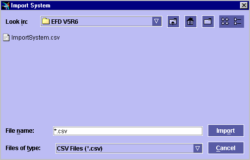
In the Electrical System Functional Definition
application, click the
Import System
 button.
| The Import System dialog box is displayed.
Note: You can import in CSV (*csv) or EFD
(*elec) format. |
 |
-
Navigate in the dialog box until you find the neutral
file to import.
-
Select the neutral file you just generated.
-
Click Import.
The selected file is analyzed and system components created.
The complete system can be viewed in the tree view.
-
Select the Save System icon to save the system
in a CATProduct type file.
|

|
![]()


