This task explains how to define the flattening parameters.
This should be done before using any other function of the Harness
Flattening toolbar.
Open a new product document using the File -> New...
command.
Choose the Product type.
-
Click Harness Flattening Parameters
 .
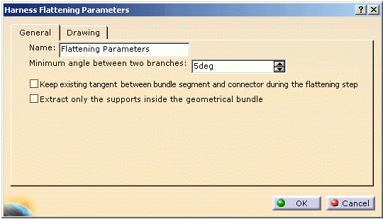
.The Harness Flattening Parameters dialog box opens on the General tab:

This tab lets you define: Name
In the specification tree, this icon
 is displayed with the name chosen in this field.
 Flattening Parameters is the default value.
Minimum angle between two branches
During the flattening process, this minimum angle is applied every time an angle between two branches is null in the 3D design. That way, bundle segments are never superposed upon one another and can easily be made out.
 The default value is 5deg.
Keep existing tangent between bundle segment and connector during the flattening step
This option gives a better flattening shape for flattening.
 By default this option is not checked.
Extract only the supports inside the geometrical bundle
The supports which do not belong to the geometrical bundle will not appear in the extracted document. This option allows you to manage two types of support:
-
The supports which must be assembled with the harness during the manufacturing step.
This type of support is created inside the geometrical bundle. -
The supports which are linked to the structure.
These supports are added to the harness during the installation step.
This type of supports is created outside the geometrical bundle.
 By default this option is not checked.
 -
-

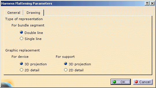
This tab lets you define:
-
The type of representation for bundle segments:
-
With Double line
 It is the default value.
 -
Or, Single line.
-
- The graphic representation you want to use when replacing
devices or supports:
- Keep the 3D projection.
 It is the default value.
 - Or, use a 2D detail previously stored in a
catalog.

In this case, the catalog name and path must be defined in the dedicated option.
- Keep the 3D projection.
-
-
Select your options and click OK to validate.
The parameters you have entered will be automatically applied to the other functions available in this workbench. You will be able to modify them at any time during your session by double-clicking the Flattening Parameters icon in the specification tree.