-
Click Interactive Grid Modeling
 .
.
The Grid Modeling dialog box is displayed with all the options grayed out. 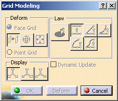
-
Click and drag the mouse in the 3D geometry.
A grid tool frames the portion of the mesh: it corresponds to the bounding box of the mesh. 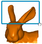

You can adjust the size of the box using the handles on each face of the box. 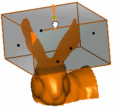
-
Now click the Deform button in the dialog box to start deforming the portion of the mesh.
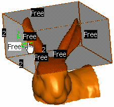
Dots are displayed in the middle of each face of the box, as well as degree and continuity tools.
Degree and continuity tools are selected in the Tools Palette:

You can click the following icons to:
 hide the
degree tools
hide the
degree tools-
 hide the
continuity tools
The resolution of the grid can be increased or decreased: right-click a degree tag and select a new degree in the contextual menu. You can also click a degree tag to progressively increase the value or Shift-click to decrease the value. -
Define the deformation mode:
-
Face Grid: you can only manipulate one entire face in the grid. Three operations can be performed:
-
 : Translation
 -
 : Rotation
 -
 : Scaling
-
-
Point Grid: you can stretch vertices and edges individually in the grid tool. The direction of the translation can be controlled using the compass.
-
The Law icon
 lets you to
manipulate more than one face by dragging the manipulator on one
face.
You can use different types of laws: identical, linear, concave, convex or bell.

The Law option is only available with the Face Grid mode. -
-
Define the Display options to control the direction in which the direction in the tool are displayed.

You can check the Dynamic Update option to control the deformation update. If unchecked (by default), the deformation is applied at the end of the manipulation. -
Depending on the deformation mode you chose, move the mouse close to any of the dots (Face Grid) or any of the vertices or edges (Point Grid). Arrows appear letting to stretch the model.
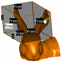
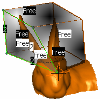
Face Grid Point Grid -
Click OK when you are satisfied with the modeling.
It could look like this: 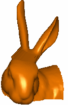
![]()