-
Click the Push/Pull icon
 .
.The Push Pull dialog box is displayed. 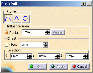
-
Define the profile of the sculpted area:
- Smooth
- Sharp
- Circular
The sculpted area can be defined by: -
a point
-
Select a point on the mesh.
-
Define the influence area around the point:
-
Check the Radius button to define a constant influence area (that is the circle around the center point) and display the magenta arrow in the geometry.
-
Use the spinners to define the push/pull magnitude.
-
Use the arrow to define the push/pull direction.
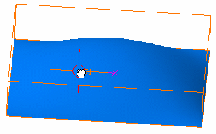
-
-
Click Apply to preview the push/pull.
The Radius button is grayed out.
- one or more curves forming a closed loop
- one or more curves and a part of the mesh boundary
- the mesh boundary
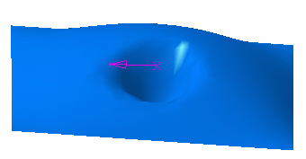

Make sure the Radius button is unchecked. -
Select the curve(s) or mesh boundary (hold the Ctrl key if you selected several curves).
In our scenario, we selected three curves. - Click a point inside the curve(s) or boudary.
-
Click Apply.
-
Define the offset:
-
Check the Show button to display the cyan arrow in the geometry.
-
Use either the spinners or the arrow to define the offset.
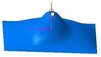
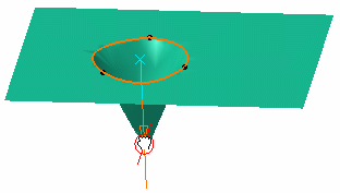
Point selection Three-curve selection 
You can click Refine to refine the sculpt by adding triangles, therefore increasing the mesh resolution. 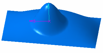
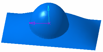
Point selection with Smooth profile
Point selection with Circular profile 
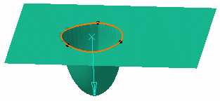
Three-curve selection with Sharp profile Three-curve selection with Circular profile 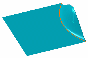
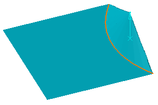
One curve & mesh boundary selection with Smooth profile One curve & mesh boundary selection with Sharp profile
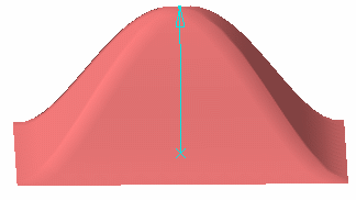
Mesh boundary selection with Smooth profile
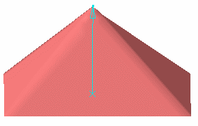
Mesh boundary selection with Sharp profile
-
-
Click OK to exit the command.
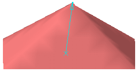
You can define the offset direction using: -
either the spinners or the cyan arrow to define a value for X, Y, and Z.
Here is an example with X= 10, Y=3, and Z=25.
-
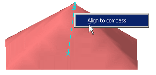
the compass: Adjust the compass to the desired direction by moving the compass on the selected mesh, then right-click the offset arrow and select Align to compass contextual menu.
The offset direction is now aligned with the compass direction.
-
![]()