Creating Lines

In this task you will learn how to create a line.
You will need to display the Horizontal (H) and Vertical (V) fields in the Tools palette, as they are displayed optionally. To do this, go to Tools > Options > Mechanical Design > Drafting > Geometry tab and select the Show H and V fields in the Tools Palette option.
1. Click the Line icon from the Geometry creation toolbar.
  The Tools palette appears, displaying the Start Point value fields:
 
2. Enter the line start point coordinates. For example, H: 1.625in and V: 0in.

3. Press Enter.

4. Enter the end point coordinates in the Tools Palette. For example, H: 2.362in and V: 0in.

OR

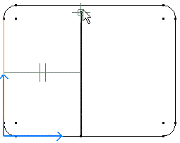
Drag the cursor to the desired location for creating the second line point. For example, drag the line end point to the top rectangle horizontal line.

In this particular case, smartpicking is used for creating the line.
The constraints in smartpicking are defined such that we can create a line parallel to one of the rectangle lines. In this case of smartpicking the parallelism symbol appears as shown here.