-
Create a new drawing sheet and tile windows horizontally using the Window > Tile Horizontally menu item.
-
Create a front view of the part.
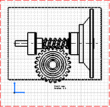
-
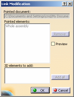
Right-click the view and select Front view object > Modify Links in the contextual menu. The
Link Modification dialog box is displayed. You can see the whole assembly is selected.
-
In the 3D product, press the Ctrl key and select the following parts:
- Roller bearing 1
- Roller bearing 2
- Slow speed shaft
- High speed shaft
- Motor adaptator
-
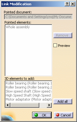
Back in the drawing, the parts have been added in the Link Modification dialog box.
-
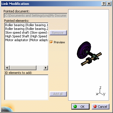
Click the Add all button.
-
Select the Preview check box to see what the 3D product looks like according to your selection.
-
Click OK.
You can see that an update icon is displayed in the specification tree of the drawing.

-
Click Update
 .
.
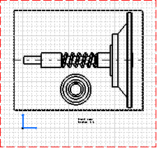
The selected parts are displayed in the front view.
Right-click and select Front view object > Modify Links. The Link Modification dialog box is displayed with links related to the parts.
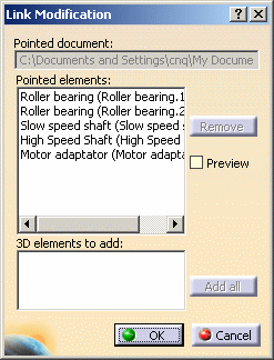
Select Motor adaptator and click the Remove button.
Select the Preview check box to visualize your 3D product.
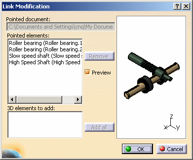
Press the Ctrl key, then click on High speed shaft and Roller bearing 1.
Click Remove.
The preview is updated.
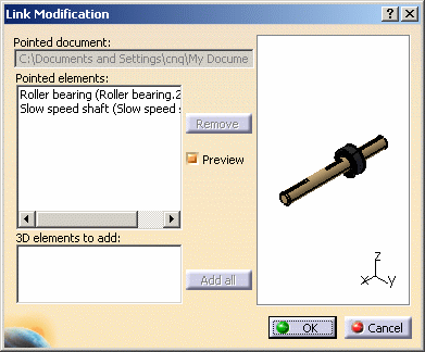
Click OK, then Update
 .
.
The front view is updated.
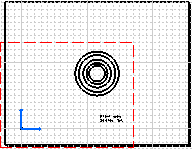

If you remove all the pointed elements, you are back to the step when you first created the front view of your product or your part. You can start selecting links again.
-
In the 3D product, press the Ctrl key and select the following parts:
- Roller bearing 1
- Roller bearing 2
- High speed shaft
-
Back in the drawing, the parts have been added in the Link Modification dialog box.
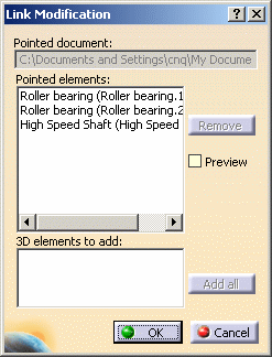
-
Click OK, then Update
 .
. -
In the 3D product, delete Roller bearing 1.
Broken links are displayed in the drawing specification tree.

-
Right-click the view and select Front view object > Modify Links.
A warning message is displayed, advising you to remove broken links.

-
Click OK.
The Link Modification dialog box is displayed with the broken link highlighted so that you can remove it.
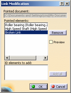
-
Click the Remove button.
-
Click OK, then Update
 :
the drawing is updated accordingly.
- As long as you do not remove broken links, you cannot modify the view at all.
- If all links are broken and removed, you are back in the Link Modification dialog box, the whole assembly being selected.
- The Front view object > Modify Links option is not available on a view from 3D.
About View's Links Modification
- All views must have the same 3D associated document.
- You can select products or sub-products if it is an assembly view, and bodies if it is a part view.
- If you want to modify links in your view when the related 3D document
is not opened, you can only remove links.
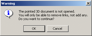
- You cannot perform Undo and Redo operations.
- If you modify the links of an exploded view, all the views generated from the assembly will be modified. For more information on exploded mode, refer to the Creating an Exploded View section.
- If you modify the links on a scene, you can select the scene only.
Would you need to select products in your assembly, you need to remove the scene's link in the Link Modification dialog box, then select products or parts' links only.
Remember you cannot mix scene links and products or parts' links. - The projection plane and the axis origin of a view created from an
assembly depends on the parent node, i.e. the common node of all view's
links.
Sometimes, when adding or removing links, the parent node changes. This can modify the projection plane and axis origin of the view. When selecting such links, a warning message is displayed:

If needed, you can reposition the projection plane using the Modifying projection plane command from the contextual menu of the view.
![]()