In
other words, you will extract drawings from the SheetMetal Design or the
Generative Sheetmetal Design workbench or the Aerospace SheetMetal Design
workbench. For more information, refer to the appropriate user's guide.
-
In the Drafting window, click Unfolded View
 in the Views toolbar (Projections sub-toolbar).
-
Select a surface on the part. This will automatically use the sheet metal reference wall plane.
If you prefer to specify which plane should be used, select the plane in the Sheet Metal specification tree.
-
Click on the sheet.
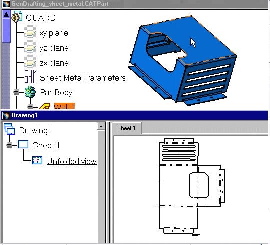
The unfolded view is displayed. It shows the axis lines resulting from bend axes, as well as bend limits. These axis lines and bend limits are represented as dashed lines.
With sheet metal parts containing holes, the hole axes (center line) are also represented on the view.
The unfolded view looks like this:

-
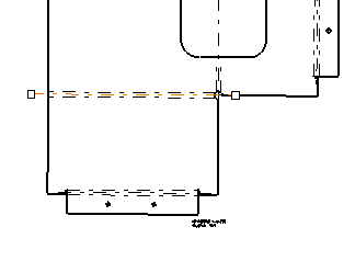
Select one of the axis lines. Manipulators appear, allowing you to modify this line.

Isolated Wireframes and 3D Points
Isolated wireframes and 3D points are not recognized as objects that can be unfolded. As a consequence, they are not displayed in an unfolded view, even if you select the options Project 3D wireframes and Project 3D points in Tools > Options > Mechanical Design > Drafting > View tab.
![]()