How associative mode works
By doing a batch conversion over an Acis/DXF 3D/Inventor/VDA-FS part,
this part is transferred into a V5 format file: a CATPart. During this
transcription, all the part structure, geometrical information as well as
original links are transferred.
After this conversion, the CATPart reproduces the 3D View of the original
part and also stores a link onto the original file. The last information
will enable the Multi-CAD Update Batch to check if V5 data are up-to-date
compared with their original data.
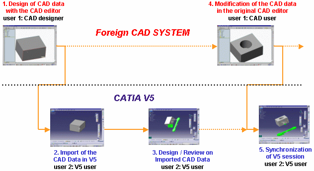
The following schema draws a parallel between the CAD System and CATIA V5. Step 3 corresponds to the modification or review of Imported CAD Data in CATIA V5.
From the Import of CAD data to the Synchronization of V5 Session:

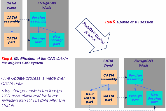
Launching the Update Batch means using the associative mode; the Batch operates on V5 data in order to update their structure or geometry according to the changes made by the Acis designer onto the original data.
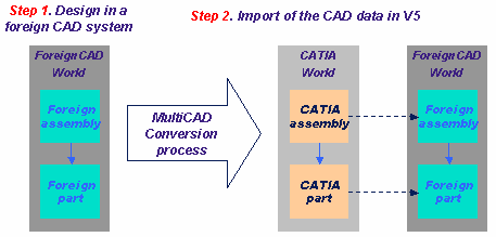
Here is a schema showing the conversion and update processes of an assembly structure when importing CAD data into CATIA V5.
Multi-CAD Conversion and Update Processes:


The associative mode is the default mode. But if you do not launch the Batch, you will use what was called the non-associative mode in the previous V5 versions.
Associative mode is useful when a user wants to maintain synchronization with structure and/or geometry changes. But if you prefer to keep your assembly as it was at the moment of the conversion, you do not need to launch the Batch. Therefore, in this case, you will not do any synchronization between V5 data and original Acis data.
How to use the Update Batch for Multi-CAD Data
This task shows you how to convert Acis/DXF 3D/Inventor/VDA-FS parts into V5 CATParts and how to keep associativity between the modified CAD data and the converted part files, in V5.
-
On Windows, in a Command Prompt window, you can launch the conversion Batch by entering the following command:
"C:\<install_dir>\intel_a\code\bin\CATDMUUtility.exe" -env CATIA.V5R10.B10 -direnv "C:\Winnt\Profiles\All Users\Application Data\Dassault Systemes\CATEnv" -f E:\tmp\acis_part.sat -part E:\tmp\Part1.CATPart
Where
-env ... is the default environment and
-direnv ... is the directory path containing this environment.
CATIA.V5R10.B10 is an example of environment name, it will vary with the level of CATIA installed.
-
Insert the CATPart into a CATProduct interactively in CATIA V5 using Insert -> Existing Component.
-
Save the CATProduct as E:\tmp\prod1.CATProduct
-
Modify the Acis/DXF 3D/Inventor/VDA-FS data in the original CAD system.
-
Launch the update Batch by entering the command:
"C:\<install_dir>\intel_a\code\bin\CATMCIReplace.exe" -env CATIA.V5R10.B10 -direnv "C:\Winnt\Profiles\All Users\Application Data\Dassault Systemes\CATEnv" -i E:\tmp\prod1.CATProduct -update
-
If you open prod1.CATProduct interactively in CATIA V5, you will be able to see the geometry modification.