in a separate or existing .CATPart document, keeping the link to the original .CATPart.
This Mirror Part is created
copying and hiding the existing Composites features in a new CATPart,
and by
adding symmetry features to the existing Composites features (only the
symmetry features are visible).
This action is to be used at the end of the
Engineering process or at the end of the Manufacturing process
(not in the
course of a designing process, to create a new part by symmetry from an
existing part).
This Mirror Part keeps a link with the original part, so that it can be synchronized with the original part, if it is modified.
- Do not regenerate a 3D Multisplice feature by editing the
feature and validating the edition with OK,
because this would regenerate the cut-pieces and delete the Mirror features previously created from the cut-pieces. - Note that:
- Producibility parameters are transferred to the Mirror Part.
- the following elements are not generated in the Mirror Part:
- Core Samples,
- Numerical Analysis,
- Exploded surfaces
- Preliminary design entities (Composites PD): they are not
usable in the Mirror Part.
As in the manufacturing preparation document, they are transferred if they are inputs of plies,
but in this case, the Composites PD node cannot be extended.
However, Full plies contour and ETBS features will be transferred (like construction geometries).
Other elements are transferred as follows:
Input elements of the geometrical features describing the Stacking:
- They are imported in the Mirror Part,
- They are put in the No Show via their father Geometrical Set,
- Only the mirrored elements are visible.
Reference surfaces corresponding to plies groups, plies, cut-pieces, ...:
- They are imported in the Mirror Part and put in the No Show as above,
- A GSD Symmetry feature is created in a new Geometrical Set named Symmetry geometries,
- The name of the symmetry feature is Symmetry of "Name of the original surface",
- Each symmetry feature is assigned to the corresponding stacking
element
(plies group, plies without cut-pieces, plies with no associative cut-pieces, cut-pieces, ...)
In the Mirror Part, symmetry is not applied to a ply with associative cut-pieces,
but is applied to its cut-pieces. As a consequence:- symmetry will not be applied to the reference surface of the
ply,
but will be applied to the reference surface of the cut-pieces. - if you want to create a core sampling on a ply with associative
cut-pieces,
select the check box Take cut-pieces into account to generate a correct result.
- symmetry will not be applied to the reference surface of the
ply,
- They are imported in the Mirror Part and put in the No Show as above,
- A GSD symmetry feature is created in a new Geometrical Set named Symmetry geometries,
- The name of the symmetry feature is Symmetry of Axis system.x,
- Each symmetry of Axis system is assigned to the corresponding stacking
element
(plies group, plies, cut-pieces, tape, core).
- The symmetry of the axis is created, with no orientation changes,
- If you want to use another rosette, you must create it and
change the orientations of the plies manually.
- They are transferred as is so that the Mirror Part points to the same
material catalog
and uses the same directions.
Stacking:
- The mirrored Stacking elements keeps a link with the original
Stacking element,
- This link is visible using the Edit>Links... command,
- You cannot replace this link but you can deactivate it,
- It is visible through Enovia for Impacted by and Impacts on.
- Each ply geometry receives a new symmetry feature, named Mirror,
placed after all the composites features (contour, limit contour, skin swapping, material excess)
coming from the original part,
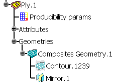
- This Mirror feature is similar to the symmetry features above,
with the difference that it lays the result of the symmetry on the symmetry of the reference surface. - It can be edited.
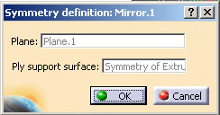

The ply direction remains the same, as the direction is expressed in the symmetry of the original rosette. - This Mirror feature is similar to the symmetry features above,
- Associative cut-pieces (i.e. with Limit Contour features):
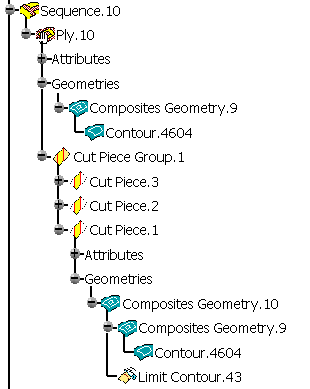
- No symmetry feature is added to the Composites Geometry of the father ply (here Ply.10),
- A Mirror feature is added at the end of the Composites Geometry of
each cut-piece
(associativity is kept).
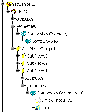
- Non associative cut-pieces (i.e. with datum curves as input to the
cut-piece contour):
- A symmetry feature is added to the Composites Geometry of the father ply,
- A Mirror feature is added at the end of each cut-piece Composites Geometry.
- Associative flatten geometry for plies and cut-pieces:
- Producibility paramaters are modified: a GSD symmetry feature is
created for the Seed point,
the seed curve and each curve of order of drape.
If the Seed point was given by Point indication, a symmetry is applied to the stored Point indication. - The Flatten Rosette and the Flatten Contour are updated as they are
computed from the Ply Geometry,
hence from the new symmetry feature in it.
No symmetry is applied to the location point of the associative flatten geometry.
- Producibility paramaters are modified: a GSD symmetry feature is
created for the Seed point,
- Non associative (manually created) flatten geometry for plies and
cut-pieces:
- a GSD symmetry feature of the flatten geometry of the original part,
named Symmetry of "name of the feature or datum",
is created in the Symmetry geometries Geometrical Set. - This symmetry feature is assigned to the corresponding ply, cut-piece or tape.
- a GSD symmetry feature of the flatten geometry of the original part,
-
Click Create Mirror Part
 in the Mirror
toolbar.
The Create Mirror Part dialog box is displayed.
Select the Part option you require.
If you select Create mirror in existing part, enter the path of the existing part.

-
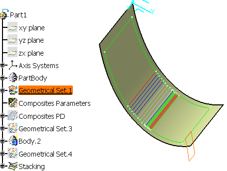
Select the Mirror plane as shown below and keep the option Create mirror in new part.
The field Plane is updated.
-
Click OK.
A message invites you to save the original CATPart at the end of this process,
to ensure synchronization will be possible in the future.
Another message warns you of possible changes in the specification tree.
Click OK to proceed.
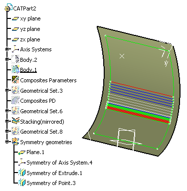
A new CATPart is created. It contains an image of the original CATPart:
all the elements (features, datum, parameters) necessary to define or
update the stacking elements are instantiated in this new CATPart.
Symmetry features are added for all the composites elements.
![]()