Some generative view style parameters are specifically available to produce customized drawings from parts designed in the Composites Design workbench. It is the administrator's job to provide suitable styles.
Note that drawings can inherit the graphic properties of the 3D View, i.e.
here the Composites part.
This applies to the contours of plies, exploded surfaces, flattens, etc. To
do so, the 3DInheritance nodes of the GVS file must be set to Yes, for
Point, Wireframe and Solid, as shown below:
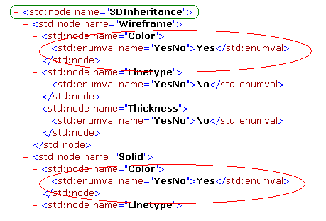
If they are set to No, the Composites features 2D projections will be
displayed in black.
install_root/resources/standard/generativeparameters.
Open the GVS1.CATPart document.
Before starting, make sure the Prevent generative view
style creation option is unselected
in Tools > Options
> Mechanical Design > Drafting > Administration tab,
prior to
generating a view in a .CATDrawing document. This activates generative view
style functionalities.
Producing a Drawing with a Generative View Styles File
-
Select Start > Mechanical Design > Drafting.
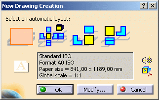
The New Drawing Creation dialog box appears. The empty sheet layout is pre-selected.
-
Click OK.
You switch to the Drafting workbench and an empty drafting sheet is created. -
For ease of use, tile the windows horizontally using the Window > Tile Horizontally menu item.
-
Click the Front View icon
 in the Views toolbar from the Generative Drafting workbench.
The Generative View Style toolbar is automatically displayed.

-
Return to the 3D document.
-
Select the entity you want to be represented in the drawing.
It can be the stacking, a Plies group, a sequence or a ply.
In our example, we select Plies Group.1 -
Then select a plane in the specification tree.
In our example, we selected xy plane.
A preview of the view is displayed in the drawing. -
Click in the drawing to validate the view creation.
The front view is created, displaying the plies of Plies group.1 as defined in the chosen generative view style.

-
Click the Offset section cut icon
 in
the Sections toolbar.
The Generative View Style toolbar is automatically displayed.
-
Select the CompositesGVSExplodedOnly style in the drop down list.
-
Sketch the cutting profile of the offset section cut, then click in the drawing to create the section.

-
Position the section cut in the drawing sheet, then click in the drawing to create the offset section cut.
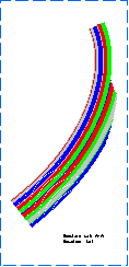
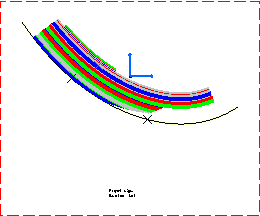
The offset section cut is created, displaying the exploded plies only as defined in the chosen generative view style.
-
Return to the 3D document.
-
Select Start > Mechanical Design > Drafting to create a new drawing sheet.
-
Click OK.
-
Click the Front View icon
 in the Views toolbar from the Generative Drafting workbench.
 -
Select the CompositesGVSFlattenOnly style in the drop down list.
-
Return to the 3D document.
-
Then select a plane in the specification tree.
In our example, we selected the yz plane. -
Click in the drawing to validate the view creation.
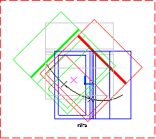
The front view is created, displaying the flatten plies as defined in the chosen generative view style.
Modifying the Generative View Style after the View is Generated
-
Right-click on the Front-view node and select Properties.
The Properties dialog box is displayed. -
In the Generative View Style list, select CompositesGVSExplodedOnly.

-
Click OK.
-
Click the Update icon
 to update the view.
The exploded plies are displayed in the drawing.
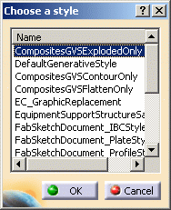
To do so, right-click the Front-view node and select Front View Object>Generative View Style>Set View Style.
Then select the appropriate style in the Choose a style dialog box.
![]()