The TransitionZone1.CATPart document will be used in this scenario.
-
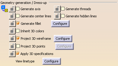
Make sure the Project 3D wireframe option is selected in Tools > Options > Mechanical Design > Drafting > View tab, prior to generating a view in a .CATDrawing document, in order to be able to visualize the ply contours and the GSD curves.
-
Select the Inherit 3D colors check box if you want the drawings to inherit the graphic properties of the 3D View,
i.e. here the Composites part. This applies to the contours of plies, exploded surfaces, flattens, etc.
If you do not select this check box, the 2D projections of the Composites features will be displayed in black.
-
Select Mechanical Design > Drafting from the Start menu bar.
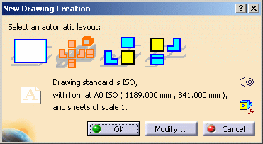
The New Drawing Creation dialog box is displayed.
-
Choose the automatic layout.
Here, we selected the All Views layout. -
Click OK.
The Drafting workbench is loaded and a drawing sheet is displayed, from the composites part you opened.
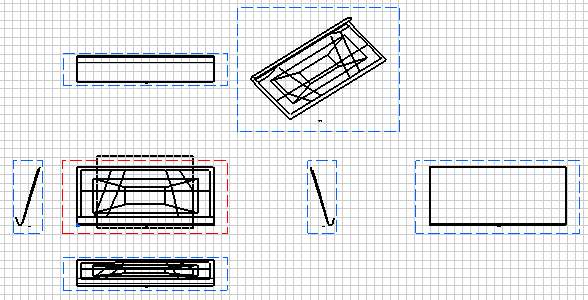
Ply contours are now represented, in addition to GSD curves.
2D Views of 3D Plies
To do this, you should have a catalog of templates for the ply annotation.
For instance, a template can include the name, the material and the direction of the ply, when another template can include the name, the material, the direction and the rosette of the ply.
-
Click the Text with leader icon
 from the Annotations toolbar (Texts sub-toolbar).
 -
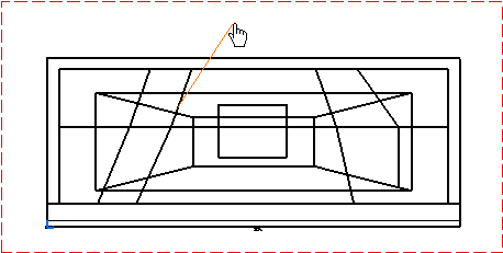
Select a curve in the Front View.
-
Click the point on the element you want the leader to begin (arrow end).
-
Right click the red frame and select Insert link template.

-
In the Insert Link Template dialog box, select the attribute you need for the annotation then click Insert.

-
Click Close once you have the required attributes.
They are displayed in the text editor.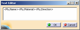
-
Click OK to create the ply's annotation.
2D Section Views
-
Click the Offset Section Cut icon
 .
. -
Select the elements required for sketching the cutting profile: points, edges (linear or circular), center lines, axes.
-
Double-click to end the cutting profile creation.
-
Positioning the section cut.
-
Repeat step 1 to 7 as described above in the 2D views of 3D plies section to create the ply annotation.
![]()