- Several views per ply
- Capability to toggle between 1 ply per sheet or 1 sequence per sheet options.
- Ply shading
- Ply annotation giving access to all the technological attributes of the ply (material, direction, rosette, sequence…)
- Available in Composites Engineering Design (CPE) and Composites Design for Manufacturing (CPM).
- If the Composites CATPart is modified (e.g. a ply group is added), you must regenerate the ply book.
- The drawing sheets and the views generated by the command
Ply Book are not associative:
- If you update one of the sheets or one of the views, the result will not comply with the initial drawing,
- If you copy/paste one sheet or one view, updating this sheet or this view will not produce a result in compliance with the initial sheet or view.
- Plies are visualized in the ply book, cut-pieces are not.
-
If not already done, explode plies you will be working on.
-
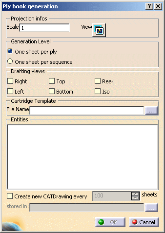
Click Ply Book
 in the Data Export toolbar.
The Ply Book dialog box is displayed.
-
Enter the required scale to ensure the drawings match the paper format.

-
Select the Generation Level you need

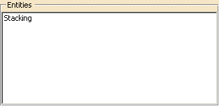
and the stacking, group of plies, sequences or individual plies and cores you want to export.
The dialog box is updated accordingly:
-
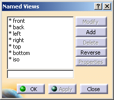
Click View to select the main 3D viewpoint that will be represented in the CATDrawings as the front view. This view is always generated in the CATDrawing.

This icon opens the Named Views dialog box:
-
Then select the optional views you require, if any.

They are computed from the main view selected in step 4, except for the Iso view that corresponds to the native isometrical view of the CATPart.
We have selected the Right view. -
Key in the path to an existing CATDrawing document that contains a cartridge that will be duplicated in each sheet and filled in with the plies information (Material, Orientation, Thickness, Name, GroupID, SequenceID).

You can use Cartridge.CATDrawing from the samples directory.
- You can provide a default path for the template in the Tools>Options>Mechanical Design>Composites Design tabpage.
- You can modify the cartridge using a VBScript macro. A sample is
provided under
C:\Program Files\DassaultSystemes\B17\intel_a\VBScript\FrameTitleBlock - To create a cartridge via a macro or interactively, you must respect
the following naming conventions:
- For the ply: TitleBlock_Text_PlyName
- For the material: TitleBlock_Text_PlyMaterial
- For the direction: TitleBlock_Text_PlyDirection
- For the thickness: TitleBlock_Text_PlyThickness
- For the sequence: TitleBlock_Text_PlySequence
- For the ply group: TitleBlock_Text_PlyGroup
-
If required, select the Create new CATDrawing every check box and key in a value.

Click... to enter a storage path. -
Click OK to generate the Ply Book. A progress bar is displayed while the Ply Book is generated.
Ply Book Description
Sheet Description
The first sheet is empty, you can add comments or any additional
information.
Each drafting sheet has the following naming convention:
- Sequence name – Ply name in ply mode
- PlyGroup name – sequence name in sequence mode
One sheet is created for each sequence (or for each ply).
The cartridge is inserted in each sheet.
Ply Representation
The reference shell of the ply appears in an exact mode for each view.
The ply is in shading mode or exact mode for each view depending on your
choice in the customizing section.
The color associated is the color of the 3D model (i.e. a color is
associated to each direction)
Rosette Representation
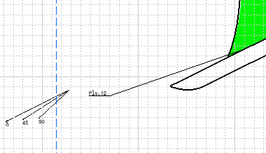
The rosette of the ply appears for each view and for each ply (It is a 2D
view of the xy axis + a 45 degree vector).
It is just a projection of the 3D local rosette of the ply in 2D. It is
located besides the plies name.
Ply Annotation
A ply name annotation appears for each ply and for each view. It is
linked to the ply with a text leader.
You can modify the location of the ply annotation and text leader in the
drafting workbench.
Example of Ply Annotation and Rosette Representation
Cartridge Information
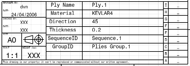
The following information appears directly in the cartridge:
- Ply group name
- Sequence name
- Material name. If all the plies of a sequence share the same material,
the name of the material appears only once.
Otherwise, the material name appears for each ply) - Direction value
- Rosette
- Ply thickness. However it does not appear for the core, it is replaced by …)
If the sequence has several plies, the information for each ply are separated with the / sign.
Only the fields that are published and that correspond to the Composites information mentioned here above are filled.
- Printing of all the sequence sheets is possible.
- Additional views or sheets must be manually inserted in the drafting workbench.
![]()