Open the Export1.CATPart document.
-
Click Ply data export as IGES or DXF
 .
.
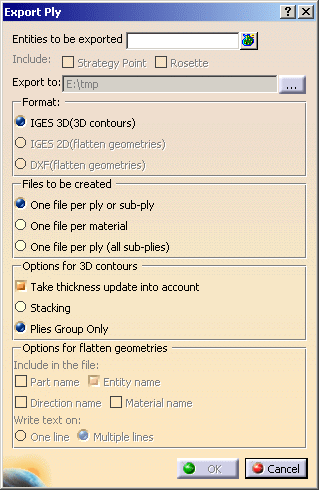
The Export Ply dialog box is displayed.
-
Select the entities to be exported (in our scenario, we selected the Stacking).
It can be a ply, a ply sequence, a plies group or a stacking.
Multi-selection of plies is possible. -
Click ... to select the directory where you want to store the export file. We have selected E:\tmp.
-
Select one export format.
Three formats are available:- IGES 3D(3D contours):3D engineering geometry and 3D manufacturing geometry.
- When this option is selected, the Options for 3D contours
are available:

- Take thickness update into account allows you to export the thickness update of the 3D geometry.
-
Two modes of thickness update are available:
-
Stacking: all the plies of the stacking preceding the selected plies are included in the export
-
Plies group Only: all the plies preceding the selected plies but in the same ply group are included in the export.
-
- IGES 2D(flatten geometries): export in 2D (flatten geometry only).
- DXF(flatten geometries): export in 2D (flatten geometry only).
- When the IGES 2D(flatten geometries) or
DXF(flatten geometries) option is selected, the Options
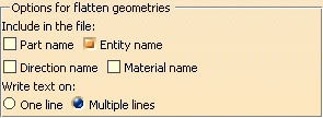
for flatten geometries are available:
- select the check boxes of the texts you want to include in the
file:
- Part name,
- Entity name, i.e. name of ply or name of ply/cut-piece,
- Direction name,
- Material name,
- then select how you want to write those texts:
- on One line
- on Multiple lines.
- Those texts will be added as text entities in the DXF or IGES 2D files and located close to the strategy point.
- select the check boxes of the texts you want to include in the
file:

To export text annotations as texts, select the Export mode option Semantic or Structured in Tools>Options>General>Compatibility>DXF or IGES 2D. -
If you have selected IGES 2D(flatten geometries) or IGES 2D(flatten geometries), the Include options become available:

You can choose to include: -
the Strategy Point: seed point defined during the producibility analysis,
-
or the Rosette: local rosette stored under each ply,
-
you can select one or both options, or none.
-
-
Choose how you want to create the file:

-
One file per ply (all sub-plies), in this case all the cut pieces aggregated under each plies are included in the file.
-
Click OK to export the ply data. The export files are created in the directory you have selected. All follow the same naming rule, that is:
Ply.number_Material_Direction.ExportType, e.g. Plies Group.1_Ply.1_KEVLAR4_45.igs
- If you open a .dxf or .ig2 file in CATIA:
A CATDrawing is displayed.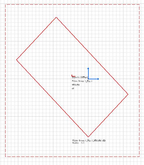
Details of the Rosette, Part name, Entity name, Direction name and Material name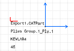
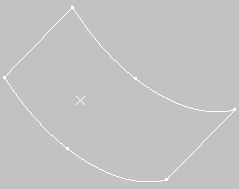
- If you open an .igs file:
A 3D curve is displayed.
![]()