 |
This task shows you how to create section views of the stacking or of
plies, without exploding the plies beforehand.
The resulting sections will be stored in the CATPart. |
|
 |
Available in Composites Engineering Design (CPE) and Composites Design for Manufacturing (CPM). |
 |
Open the PlyExploder1.CATPart
document. |
 |
-
Click Ply Section
 . .
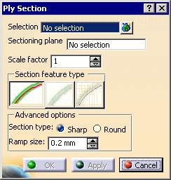
The Ply Section dialog box is displayed:
-
Select the
elements to section.
The Selection field is updated.
They can be the complete stacking or a selection of plies groups.
Multi-selection is available.
-
Select the
Sectioning plane. i.e. a GSD plane.
A contextual menu is available to create one.
-
If required, key in a
Scale factor, i.e. the
factor by which the thickness of the element (ply or insert) is multiplied
in the section view as shown by the arrow in the picture below:

|
|
 |
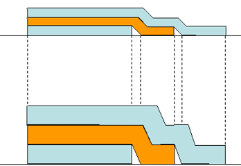
The Scale factor introduces a deformation of the section as shown
below:
At the top, the Scale factor is equal to 1
at the bottom, it is higher than 1
 |
|
|
-
Choose a
Section feature type:
Section type
-
If required, choose a :
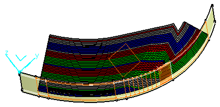
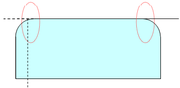
- Sharp: the angles of the ply sections remain sharp:
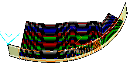
- Round: all angles of the ply sections are rounded:
|
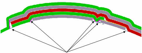
| and a Ramp size, i.e. the length of the small ramps
added at the end of each ply as shown by the arrows below: |
 |
-
Click Apply to visualize the ply sections, and
OK to create them.
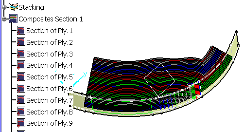
Note that:
- one output feature is created for each ply, even if it has
several sections, as show by the arrows below:

- inserts are mapped from their original position in 3D to their
position in the section cut as shown below:

- however, the shape of the insert in the section cut will not be
exactly the same as the section cut of 3D shape of the insert, as
will be morphed on the plies sections below,
- the scale factor deforms the inserts as it deforms plies,
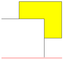
- the following two types of inserts are not supported:
- inserts with concave sides:

- inserts with a 90 degree angle shape:
- Ramps tangent to the normal of the reference curve can lead to
instabilities:
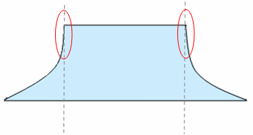
or
|
|
|
|
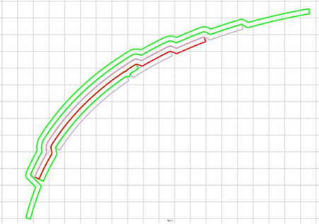
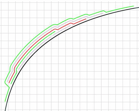
If a CATDrawing view points to a ply section and corresponds to the same
plane as the ply section, the ply section will be visible in the CATDrawing
as illustrated below:
- Surfacic or Block linear ply section:
- Light linear ply section:
|
|
 |
