![]()
-
Click the Solid From Plies icon
 .
.
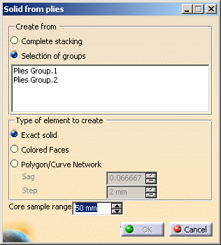
The Solid From Plies dialog box is displayed.
-
Select Selection of groups to create a solid or a polygon from a group of plies.
-
Select Plies Group.1 in the list.
-
Select Exact Solid.
-
Click OK
As a result, an exact solid of the plies is created.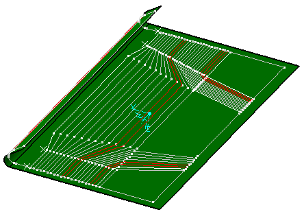
Plies Group.1 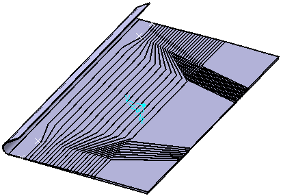
Solid created from the Plies Group.1
they are defined on the same reference shell and share the same drapping direction.
If not, one solid exact is created per group of plies.
-
Open the ModifyPlies1.CATPart document again.
-
Select Colored Faces.
-
Click OK. The solid is created as datum surfaces representing each thickness found, as illustrated below:
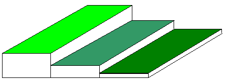
Each surface has its own green hue, the surface corresponding to the smallest thickness being the darkest, the surface corresponding to the largest thickness being the lightest.
Each surface has the name of the thickness it represents.
-
Open the ModifyPlies1.CATPart document again.
-
Select Polygon curve network.
- In a group of plies, if some plies are not defined on the same
reference shell as the group,
you are warned that only the plies lying on the same shell as the group will be taken into
when refining the polygons or the curves network.
However, they will all be taken into account
- If you created a polygon from the whole stacking, you might want to
refine the tessellation.
To do this, use the up and down arrows to enter the value you need to define both parameters :
-
Enter the required depth of the core sampling in the Core Sample Range field.
-
Click OK to create the polygon.
As a result the polygon is created with a network of curves corresponding to:- the areas where the thickness is constant,
- the areas where there is a thickness variation (slope).
![]()