Attribute Driven Graphic Replacement
|
|
This task explains
how to add graphic replacement to 2-D drawings that you generate. The graphic replacement settings in your GVS file enable you to view boundary attributes. These boundary attributes display in your 2-D drawings as offset curves and patterns. (The appearance of these 2-D drawings is controlled by drawing production settings you add to a GVS file stored in XML format.) |
|
|
|
Before you can use this process, you need to set Options as follows: From the menu bar, select Tools - Options - Mechanical Design - Drafting. Select the Administration tab and under Generative View Style, uncheck the option Prevent Generative View Style Usage. |
|
| The default file provided with this
application is called CompartmentAndAccessSample.xml.
This file is located in the directory ...intel_a\resources\standard\generativeparameters\SAMPLES. Copy the default XML file from the SAMPLES directory, and place the copy in the generativeparameters directory. You need to customize this file to view your specific boundary types with the desired graphic properties. Do not make changes to the original file. Settings are located in a section of the file under the heading Attribute Driven Graphic Replacement of Boundary. Use a text editor to add or change the settings in the XML file. |
||
In the sample file, three boundary types are
supported:
Settings for each boundary type are listed in separate sections: Wall Boundary Data, Deck Boundary Data, Overhead Boundary Data. The internal names of the user-defined boundary types (for example, CATCptWallBoundary, CATCptDeckBoundary, CATCptOverheadBndry) are defined in the Compartment and Access CATfct file (CATCompAccessSample.CATfct). The default boundary type (CATCptBoundary) is defined in the CATCompAccess.feat file. |
||
|
|
There are two types of attribute driven graphic replacement settings: edge generation and pattern generation. They appear in the GVS files as:
|
|
| BoundaryEdgeData: You can have a boundary edge if there is only one curve, such as a line, representing the boundary in the drawing. This creates an offset curve towards the center of the compartment. The offset curve is re-limited at the ends by the same offset value as specified for the offset curve itself. The graphic properties (color, line type, and thickness) for the offset curve are based on the boundary attributes specified in the GVS file. | ||
| BoundaryPatternData: You can have a boundary pattern if the curves representing the boundary in the drawing form a closed contour. This creates an area fill with the profile consisting of the curves representing the boundary. The type of the area fill is based on the boundary attribute specified in the GVS file. If the attribute is not found in the boundary object, or the attribute value does not match any of those specified in the GVS file, or the pattern specified in the GVS file does not exist, the area fill is not created. | ||
In the GVS file, the
Attribute Driven Graphic Replacement of Boundary section lists the
graphic replacement settings under the node name:
Enable indicates whether or not to apply graphic replacement. Values are Yes or No. The following applies to each boundary type:
|
||
Attribute MappingAttribute mapping is how you define the actual boundary properties that display in your 2-D drawing. The following is an example of attribute mapping settings in the GVS file:
Value_x is a possible value for an attribute node name (such as Attr_1) corresponding to graphical properties used for edge generation, and pattern generation. Each attribute node name can have as many as 20 possible values (shown as Value_1 through Value_20). Each value represents a different graphical appearance. As an example, Insulated is an attribute name for a particular boundary type, and is contained in Attr_1. Insulated is used to set line graphical properties under BoundaryEdgeData, and pattern properties under BoundaryPatternData. Its value (Value_1) could be defined as Yes. The GVS file lists the properties for edge generation and pattern generation that correspond to Value_1.
NOTE: Attribute names in the GVS file (such as Insulated) must be internal names that match the attributes on the Compartment Access tab of the Properties dialog box. Values set in the GVS file (such as Yes and No) must correspond to the attribute values that display in the Properties dialog box. Pattern names are those used in drafting. Insulated also could have a Value_2 defined as No. The GVS file lists the properties for edge generation and patterns generation that correspond to Value_2.
|
||
Viewing the Boundary Attributes in your 2-D DrawingAs explained above, to apply graphic replacement to 2-D drawings and view boundary attributes, you need to define the actual boundary settings in your GVS file. The following are examples of attribute settings in the GVS file, and their corresponding graphical appearance in the 2-D drawing. Under a wall boundary (such as BoundaryType_1):
Under AttrMapping:
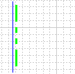
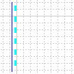
When you drop the wall boundary on edge, it displays in the 2-D drawing as follows:
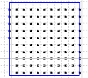
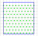
When you drop the wall boundary, using its surface as a dropoff plane, it displays in the 2-D drawing as follows:
When you drop the wall boundary on edge, it displays in the 2-D drawing as follows:
When you drop the wall boundary, using its surface as a dropoff plane, it displays in the 2-D drawing as follows:
|
||
|
|
||