i.e. points, vectors representing axis or tool geometry for measurement operations.
- is available for all machining operations with the exception of Lathe machining operations.
- is available even if the tool path is unlocked.
Open Block.CATProcess from the samples directory.
-
Select a tool path or an operation.
-
Either click Create Geometries
 in the
Tool Path
Management toolbar,
or select Create Geometries in the Tool path object contextual menu.

The contextual menu is available on tool paths only. -
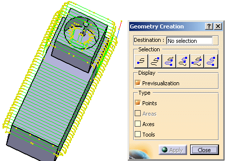
The tool path and the dialog box are displayed:

-
By default, the previsualization of points is requested.
-
Place the cursor on the Destination field and select a destination body.
-
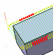
Select an area of the tool path:
-
push the button shown below,

-
pick the first and the last points of the selection.

-
-
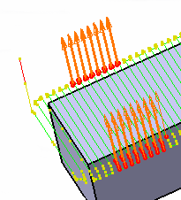
Select Axes in the Creation box. They are displayed on the tool path.

-
Click Apply, the axes are created under the Geometrical set Sweeping.1 .
Click Close to exit the action
since it would create the elements of the type selected.
![]()