|
|
When you generate graphic replacement for structure objects, various view types are available, depending on the object. These view types have near side and far side parameters. |
| NearSide and FarSide Parameters | |
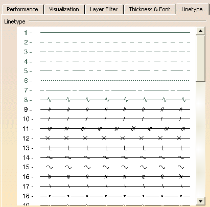
To understand this index and to see the available line types: Select Tools - Options - General - Display from the menu bar. Select the Linetype tab. To customize this array, refer to Customizing Settings in the Infrastructure User Guide.
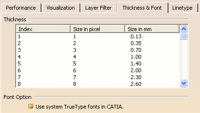
To understand this index and to see the available line line thicknesses: Select Tools - Options - General - Display from the menu bar. Select the Thickness and Font tab. You can see that 2 (the default) is equal to 0.35mm. To customize the line thicknesses array, refer to Customizing Standards in the Infrastructure User Guide. |
|

