This task shows how save the generated geometry as a DXF document.
To perform this scenario, you can open any sheet metal sample provided in this user's guide.
-
Click Save As DXF
 .
.The Select a DXF file dialog box is displayed allowing you to navigate to the correct location. 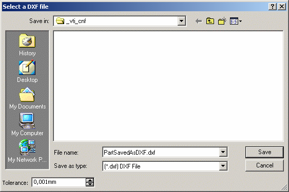
-
Indicate the correct path and file name (we saved it as PartSavedAsDXF.dxf).
-
If needed, modify the Tolerance with the up and down arrows.

The tolerance is used to compute circles and lines. The closer to 0 mm the tolerance is, the better circles and lines are represented in the drawing. 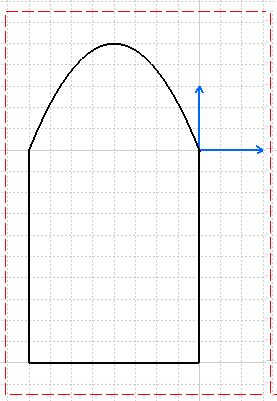
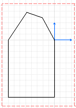
DXF file saved with a 0,1mm tolerance DXF file saved with a 10mm tolerance 
A tolerance set to 0 mm implies that the discretization of splines is impossible : in that case, curves are shown as circles. 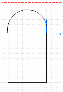
DXF file saved with a 0mm tolerance -
Click Save.
The geometry has been saved, and can be imported as a DXF file in any system supporting this type. -
Click File -> Open.
-
From the File Selection dialog box, choose the .dxf file type, then select the saved part (PartSavedAsDXF.dxf).
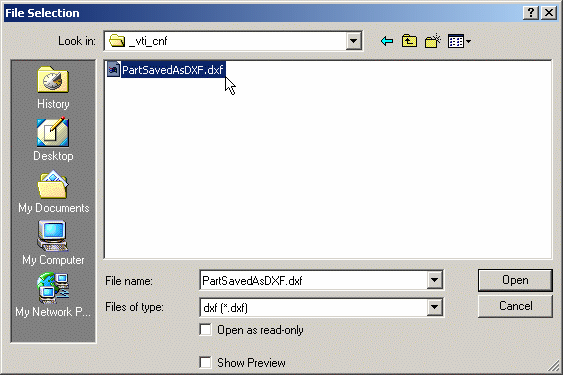
-
Click Open.
The unfolded view of the part is opened within the Drafting workbench, because the .dxf type is recognized as being a drafting type of document. Note that the axes of bends and planar hems, tear drops, or flanges are automatically displayed on the drawing. 
Refer also to DXF/DWG Settings from the Infrastructure User's Guide. 
The geometry saved as a DXF document is only an extraction of the outline of the part : it does not include complex features such as holes, chamfers and stamps.
![]()