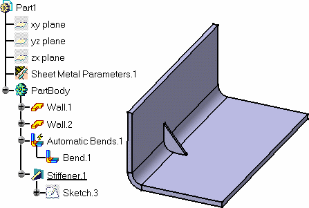
For the Sheet Metal Design workbench, open the
Stiffener1.CATPart document.
For the Generative Sheetmetal Design workbench, open the
NEWStiffener1.CATPart document.
- Part Design features can be created before Sheet Metal features.
- a Part Design feature can also be created after Sheet Metal features as long as the part is in folded view.
- in the unfolded view, the Part Design feature will not be displayed.
- it is no longer possible to create Sheet Metal features after this last Part Design feature in folded view.
-
Create two walls with an Automatic or Conical Bend for the Sheet Metal Design workbench or two walls with a Cylindrical or Conical Bend for the Generative Sheetmetal Design workbench.
-
Switch to the Part Design workbench.
-
Launch the Sketcher and draw an oblique line in the yz plane.
-
Click Stiffener
 .
.
-
Switch to the Sheet Metal Design workbench or to the Generative Sheet Metal Design workbench.
-
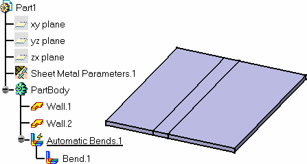
Click Fold/Unfold
 .
.
The stiffener is not displayed on the unfolded view. 
To add a Generative Sheetmetal Design feature and switch to the Sheet Metal Design workbench or to the Generative Sheetmetal Design Design workbench, select the Bend for example and right-click the Define In Work Object item. The Generative Sheetmetal Design feature will be added after the Bend but before the Stiffener.
![]()