For the Generative Sheetmetal Design workbench, open the SheetMetalDrafting1.CATPart document.
Make sure you have an appropriate Generative Drafting license. For more information about this workbench, refer to Generative Drafting User's Guide.
Make sure that the Generate axis option is checked in the Tools -> Options -> Mechanical Design -> Drafting -> View tab, prior to generating a view in a .CATDrawing document.
![]()
-
Click
 or select File -> New...
 -
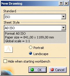
Select the Drawing type and click OK. The New Drawing dialog box is displayed.

-
Click OK. The drawing sheet appears.
-
Tile the windows horizontally using the Window -> Tile Horizontally menu item.
-
Click Unfolded View
 in the Projections toolbar from the Generative Drafting workbench.

This icon is active in the Projections toolbar provided you have a Generative Sheetmetal Design licence.
-
Choose the xy plane in the Sheet Metal specification tree. A preview of the view is displayed in the drawing.
-
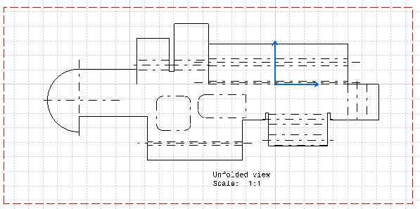
Click in the drawing to validate the view creation. The unfolded view is displayed with the planar axes and BTLs of bends and the stamps representation.


- You will note that the hem is not represented in the drawing. This is due to the fact that non-canonical flanges are not represented since they do not generate planar and cylindrical faces only.
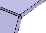
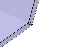
- You cannot generate neither a section view nor an
unfolded view of an extrusion including the following
confusion areas.


To avoid this problem, create a bend between the two walls.