This task explains how to create a Sheet Metal part in an Assembly context.
For the Sheet Metal Design workbench, open the
Scenario2.CATProduct document.
For the Generative Sheetmetal Design workbench, open the
NEWScenario2.CATProduct document.
Open the part in the Assembly Design workbench (Start -> Mechanical Design -> Assembly Design).
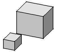 |
-
Right-click Product1 in the specification tree and select Components -> New Part...
Provided the Manual Input option is checked in Tools -> Options -> Infrastructure -> Product Structure, Product Structure tab, the Part Number dialog box is displayed:
-
Enter Part3 in the New part Number field and click OK.
A New Part dialog box proposes two locations to define the origin point.
For more information, refer to Inserting a New Part, in the Product Structure User's Guide.
-
Click No to locate the part origin according to the Product1 origin point.
Make sure you are in Design Mode: - Select Product1
- Choose Edit -> Representations ->Design Mode
- Expand the tree and activate the Part3 Part body by double-clicking.
-
Switch to the Sheet Metal Design workbench or to the Generative Sheetmetal Design workbench.
-
Click Sheet Metal parameters
 to create the Sheet Metal characteristics for the part:
 -
1mm for the Thickness
-
3mm for the Bend radius
-
Linear for the Bend extremities
and click OK.
-
-
Choose the Tools -> Options -> Infrastructure -> Part Infrastructure, General tab and check the Keep link with selected object option, then click OK.
-
Click Sketcher
 and select the zx plane.
 -
Click Profile
 .
. -
Sketch the profile and set the constraints as shown below:
- 5mm between the Sheet Metal vertical walls and each pad
- 0mm between the Sheet Metal horizontal walls and each pad top
- 0mm between the last point of the Sheet Metal sketch and the right pad side.
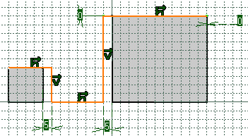
-
Click Exit
 to return to the 3D world.
 -
Click Extrusion
 .
. -
Select the Sheet Metal profile.
The Extrusion Definition dialog box appears. 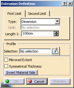
-
Enter 70mm for Length1 then click OK.

The Material Side should be set to the outside. -
Perform this step only if you are using the Sheet Metal Design workbench: click Automatic Bends
 .
.The bends are created. The new features are shown in the specification tree: - Extrusion.1 with five walls
- Automatic Bends.1 with four bends (for the Sheet Metal Design workbench only).
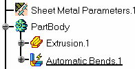
The Sheet Metal part looks like this: 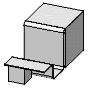
![]()
