-
Multi-select the point to locate the hole and the non-planar face (or non-planar face if working in Functional Molded Part) on which you wish to create this hole.
This operation creates a coincidence constraint setting the hole's position on the face. -
Click Hole
 if you wish to create a hole in Part Design, or click Hole
 to
create a hole in Functional Molded Part.
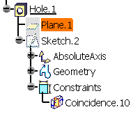
The application creates a plane which is tangent to the selected face at the selected point. This plane will be used as support for the positioning sketch. -
In the Hole Definition dialog box, define the hole shape and enter the parameter values you want to use.
-
When done, click OK to create the hole.
The plane tangent to the face is not visible in the 3D area, but appears in the specification tree. You cannot edit it.


-
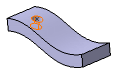
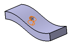
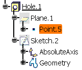
Modify the point's location:
The hole is moved accordingly.
- In case you select the face and then create a point by clicking on
the face, the point is not constrained but associativity is ensured
between the hole and the face.

- The capability explained in this task is not available when editing holes created with versions prior to Version 5 Release 16.
- Concerning power-copies, do not use holes on non-planar surfaces as input data: it is not possible to instantiate these element types.