Penetration Management Setup

|
This task explains
the setup process for defining a penetration cutout sketch, and identifies
some of the processes involved. Penetration management uses design rules
that are Knowledgeware-based. To modify the sample rules provided with
this application, or to create new design rules, you must know how to use
Knowledgeware. Read the documentation for that product to get more
information. In addition, you must incorporate certain data particular to
this application when creating new rules. That is explained below. You may
also need to refer to ENOVIA-LCA documentation for ENOVIA-specific tasks.
If the Penetration Management Tools toolbar is not displayed then click
View - Toolbars and select it. |
 |
Penetration
management refers to the process of routing a pipe or a duct, as an
example, through a structure. If you are working with a ship, for
instance, you may need to create penetrations through bulkheads, move
objects, or reroute your pipe or duct, in order to do so. The penetration
management function works within the ENOVIA environment only. You must be
in the ENOVIA Product Structure. |

|
1. |
The Penetration Management function uses
the following:
- Penetration Openings Catalog (Openings.catalog)
- Penetration Shapes Catalog (PenShapes.catalog)
- Penetration Cutout Rules (PenetrationCutoutRules.CATProduct)
These files are located in ...intel_a\startup\components
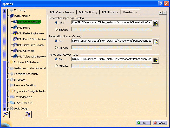
Set your Tools Options to reflect the location and names of these
files.
From the menu bar, select Tools - Options - Digital Mockup - DMU
Space Analysis
Select the Penetration tab, and set the location and file information.
 |
|
2. |
The outlines of openings are
dependent on the shapes defined in the Penetration Shapes catalog. You
cannot define an outline in the design rules that does not have a
corresponding shape in the catalog. Shapes defined in the sample catalog
are: oblong, round, rectangular, square and rectangular radius corner. You
can change the values of the parameters of the shapes in the catalog, and
you can add new shapes to it. You can remove, replace or rename the sample
shapes. Each shape is a parametric part created with the Part Design
product, and is stored in the same directory as the catalog. The oblong
shape document, for instance, is OblongShape.CATPart. See Part Design
documentation for information about using that product.
To add a shape you must create it with Part Design and store it in the
catalog using standard catalog building procedures. See Creating a Catalog and associated tasks in the Catalog section to
learn more about creating and modifying catalogs. These are standard
parametric parts and there are no special requirements for building them.
When building new shapes you should note that the description name you use
in the catalog is the name that will display when you are creating a
cutout sketch. |
|
3. |
Most penetration cutout designing
will be done using the design rules, although you have the capability of
manually defining cutouts, as explained later in this section. The rules
work with the shapes in the catalog to determine the final size of the
opening. You can add various parameters to the rules using Knowledgeware.
However, the function of the sample rules supplied with this application
is mainly to determine the shape of the outline, based on the shapes
available in the catalog; and calculate the size of the opening. The
cutout size is calculated from the sizes of the objects involved in the
penetration, with the addition of required clearances. |
|
4. |
Design rules can be modified, and
new ones created, using Knowledgeware. However, there are certain points
you must incorporate in a design rule for it to work correctly with this
function. The following information is meant for an administrator, or
whoever is creating the design rule. You can see examples in the sample
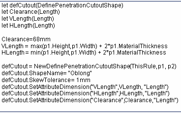
rule, which is reproduced below. A penetration cutout rule should:
- Create a variable (defCutout) to hold the
DefinePenetrationCutoutShape object, which will communicate the cutout
definition to the penetration management command.
- Calculate the size of the cutout, using attributes of the
penetrating and penetrated objects.
- The NewDefinePenetrationCutoutShape function creates the temporary
object that holds the cutout definition. The penetrating object (p1) and
penetrated object (p2) are specified.
- The ShapeName attribute selects the parametric part that defines the
shape.
- The SkewTolerance attribute sets the allowed SkewTolerance for the
penetration.
- The SetAttributeDimension function (or another SetAttributeXXX
function) specifies a parameter name in the parametric part, and its
value. This function is used repeatedly to set each parameter of the
parametric part.
A sample rule is reproduced below:

|
|
5. |
The CATIA Domain Discipline Table
is used to associate a CATIA model domain to an industrial discipline
identified in your company.
You are provided with a sample table located in:
...intel_a\reffiles\DomainDiscipMappingTable.xml
This table is often sufficient for your requirements, but you can
modify it to change the discipline names or add a CATIA model domain. Use
any text editor to modify the DomainDiscipMappingTable.xml
file. After editing, save the file in the reffiles directory.
The following is a sample of the file format:

The ENOVIA discipline names are also user-defined, and must correspond
to the discipline names in the ENOVIA Penetration Discipline Table located
on the ENOVIA code server in ...\(platform)\reffiles\PenetrationDisciplines.xml.
(The paths for all platforms are identical with the exception of the
platform identifier. For example, on AIX the platform identifier is
.../aix_a/reffiles.)
The ENOVIA discipline names are used in ENOVIA to look up the
penetration discipline code. The penetration discipline code is used in
the Penetration ID, and for assigning workflow activities in a Penetration
workflow process. |

|
![]()