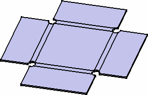
Defining the Bend Corner Relief

This section is only available for the Sheet Metal Design workbench, NOT for the Generative Sheetmetal Design workbench.

This section explains how to change the bend corner relief.

Open CornerRelief01.CATPart if you are using the Sheet Metal Design workbench.

Within the Tools -> Options -> General -> Parameters -> Knowledge tab, check the Load Extended Language Libraries option.

  1. Click Sheet Metal Parameters .
    The Sheet Metal Parameters dialog box is displayed.
    The third tab concerns the bend corner relief.
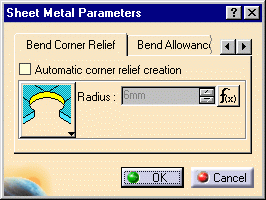
By default, no corner relief is created when a bend is created. Check the Automatic corner relief creation option to activate this creation every time a bend is created.
Three corner relief types are available. Select the icon corresponding to the requested type:
  •  
square: the square corner relief is created using the bend limits. Its dimensions are defined by the width of the unfolded bends.
  •  
circular: its center is located at the intersection of the bend axes. For that option, a radius is proposed by default. It is equal to the bend radius + the thickness. To change it:
  • Select Formula -> Deactivate from the contextual menu of the input field and enter a new value,
  • click on the button and enter a new formula.
  •  
:
triangular: the triangular relief is created from the intersection point of the inner bend limits towards the intersection points of the outer bend limits with each wall. 
The corner relief is not previewed during its creation.

The corner relief is taken into account in the unfolded view.

  • For better result, you should select the Maximum Bend Extremities option when creating corner relief.
  • These parameters are applied to each corner relief created or to be created, except to those with that have been redefined, or the locally defined corner relieves.