To determine the geometric properties of an object when it is imported from Process Engineer:
- DPM first searches for its representation in the graphicname_alt1 attribute. If this attribute is not empty, it will provide a DPM-defined representation of the object (such as CATPart, model, CATProduct, CGR etc.).
- If no such representation exists in the graphicname_alt1 attribute,
- For a product: the CAD File attribute is then queried. This attribute is used for representation supported by Process Engineer (CGR, JT, etc.) of the product.
- For a resource: the graphicname attribute is then queried. This attribute is used for representation supported by Process Engineer (CGR, JT, etc.) of the resource.
- If no representation is found, the product/resource is represented as an empty node on the PPR tree with no graphical representation in the 3D viewer.
DPM uses the value of this attribute to load the geometry of the entity. The object will then be loaded:
- As a shape representation if the file is a CGR or a model of another CAD type file (a DPM equivalent of the Process Engineer entity is created with the associated file as its representation).
-
As an external component for CATPart and CATProduct (so the Process Engineer entity is replaced by the root of this associated file).
In the example below:
- When Part 1 was brought into DPM, the graphicname_alt1 attribute was found to be empty, but the CAD File attribute defined a CGR as its representation. This can be seen via the Manage Representations dialog (as shown).
-
When Part 2 was brought into DPM, the graphicname_alt1 attribute defined a CATPart as the graphical representation of the product. Therefore, the part and its sub-assembly can be seen in the PPR tree (highlighted in the blue box).

Notes
-
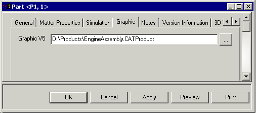
When defining the graphicname_alt1 attribute in Process Engineer, either an absolute path or a relative path may be defined.
An absolute path specifies the full path to the graphic representation, as shown in the example below:

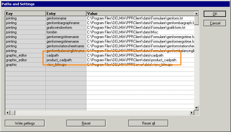
When a relative path is specified, the root path is taken from the current cadpath and product_cadpath settings in Process Engineer:

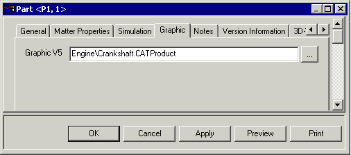
The relative path specified for the graphicname_alt1 attribute is appended to the path defined for cadpath and product_cadpath to locate the graphic representation. The following example of a relative path would then resolve to:
C:\Program Files\DELMIA\PPRClient\data\cadpath\Engine\Crankshaft.CATProduct

-
When loading geometry defined with relative paths, either of the following conditions must be satisfied:
- The values of the
cadpathandproduct_cadpathvariables each have a trailing backslash ("\") character, or the relative pathname for the product/resource geometry begins with a backslash ("\"). - The values of the
cadpathandproduct_cadpathvariables each do not have a trailing backslash ("\") character, and the relative pathname for product/resource geometry does not begin with a backslash character ("\").
Geometry will not be successfully generated in the V5 cache in the event that (a) the values of the
cadpathandproduct_cadpathvariables have a trailing backslash character at the end and (b) the relative pathname for product/resource geometry begins with a backslash. - The values of the
-
If a resource has a work system component associated with it, the geometry of the work system component will be loaded in DPM when the resource is loaded in DPM. The following geometry formats are supported:
- .cgr
- .objekt
- .bom
- .jt
- .primitive
- .wrl