![]()
This task explains how to measure the length, radius and angles of an arc drawn through three points.
![]()
Insert the following sample model files: ATOMIZER.model, BODY1.model, BODY2.model, LOCK.model, NOZZLE1.model, NOZZLE2.model, REGULATION_COMMAND.model, REGULATOR.model, TRIGGER.model and VALVE.model.
They are to be found in the online documentation file tree
in the common functionalities samples folder cfysm/samples.
-
Click Arc through Three Points
 in the DMU Space Analysis toolbar or select Analyze > Arc
through Three Points from the menu bar. The Measure Arc
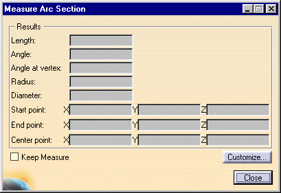
Section dialog box appears.
-
A Keep Measure option (
 by default, the check box is cleared ) in the dialog box lets you keep the current and
subsequent measures as features. This is useful if you want to keep
the measures as annotations for example.
 -
Double-clicking an existing measure lets you re-edit the presentation of the measure, review information in the dialog box or delete measures.
P1 Functionalities
In DMU-P1, the Measure Tools toolbar also appears.

This toolbar has two icons:
-
Measure Dialogs
 :
lets you show or hide the associated dialog box.
 -
Exit Measure
 :
lets you exit the measure. This is useful when the dialog box
is hidden.
-
-
Select three points along a curve or an arc.
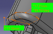
An arc is fitted through the three selected points and is displayed along with its center point. The arc length, angle and radius are also visualized.
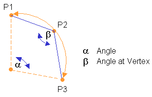
The dialog box is updated and now gives the length, angle, angle at vertex and radius or diameter of the arc as well as start, end and center point coordinates.
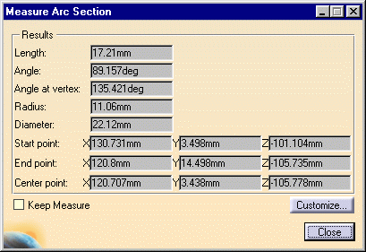
The number of decimal places, the display of trailing zeros and limits for exponential notation is controlled by the Units tab in the Options dialog box (Tools > Options, General > Parameters and Measure). For more information, see the Infrastructure User's Guide.
Notes:
-
The appearance of the cursor
 changes to
reflect the measure command that you are in. A number (1, 2 then 3)
also helps you identify where you are in your measure.
 -
Dynamic highlighting
 as you move the cursor over
geometrical entities helps you locate points. As you move over
edges, the edge (and not the surface) is highlighted.
-
-
If necessary, adjust the presentation of the measure. You can move the radius line and text anchor point as well as the texts of the measure.

The Properties command (Graphics tab) lets you change the fill color and transparency as well as the color, line type and thickness of measure lines.
Note: You cannot vary transparency properties, the current object is either the selected color or transparent. -
(Optional) Customize your measure if needed. To do so (at any time):
-
Click Customize... in the Measure Arc Section dialog box and,
-
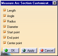
Set your display in the Measure Arc Section Customization dialog box
 By default, all results are displayed
-
-
Click Close when done.
![]()