|
|
|
|
|
|
|
The behavior of this command is to add a row at the end of the design table file with associated parameters values. For not associated columns, an empty cell is added.
| KwrAddARow.CATPart |
| KwrAddARow.xls |
![]()
-
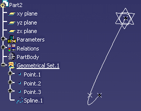
Open the KwrAddARow.CATPart file. The following image is displayed.

-
Click the Design Table icon (
 ).
). -
Select Create a design table from a pre-existing file and click OK.
-
In the opening File Selection window, select the KwrAddARow.xls file and click Open.
-
Click Yes in the Automatic associations window: The design table opens. Click OK to close it.
-
Click the Asynchronous Relations Update icon to update Formula.1.
-
Under the Design Tables node, double-click Configuration=1. The Edit Parameter dialog box is displayed.
-
Click the Design table icon in the Edit Parameter dialog box: The Design Table window is displayed.
-
In the dialog box, select the second configuration (line 2), click Apply, and OK twice.
-
Right-click Formula.1 in the specification tree and select Local Update.
-
In the Specification tree, right-click DesignTable.1 and select DesignTable.1 object>Deactivate. The design table is deactivated.
-
Modify the spline:
|
||||
|
Point 1 | Point 2 | Point 3 | |
| X | 0 | 100 | 50 | |
| Y | 0 | 100 | 50 | |
| Z | 0 | -100 | -226 | |
|
||||
-
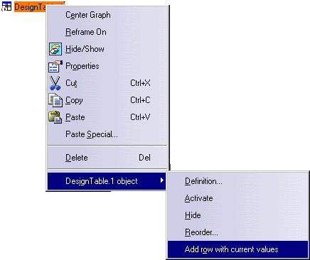
Add the new configuration to the design table. To do so, right-click DesignTable.1 in the specification tree and select DesignTable.1 object>Add row with current values.

-
Right-click DesignTable.1 and select DesignTable.1 object>Activate.
-
Double-click Configuration=1 under DesignTable.1 and click the Design Table icon (
 ).
). -
In the DesignTable.1 window select the configuration that you have just added and click Apply and OK twice. The spline is updated accordingly.
![]()