 |
This command is only available with the FreeStyle
Optimizer. |
 |
This task explains how to deform
a set of surfaces in one operation. |
 |
Open the
FreeStyle_Part_36.CATPart document. |
 |
-
Select the surfaces to be deformed,
using the Control key for multi-selection.
-
Click the Global Deformation icon:

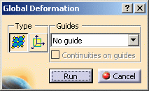
The Global Deformation dialog box
appears, into which you can specify deformation options: using an
intermediate patch or a user-defined axis.
In this case, use the default option: intermediate patch (
Intermediate surface use icon). |
 |
-
Click Run in the Global Deformation dialog
box.
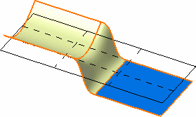
| A transparent patch with control points and mesh
lines is displayed. It represents the intermediate surface bounding box. |
 |
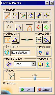
The Control Points dialog box is
displayed. Use it to define the type of operation to be performed on the
control points:
- Support defines the type of
translation to be applied.
- Law defines the type of deformation
that is to be applied when several control points have been selected.
|
 |
-
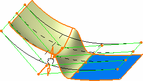
Use the control points and the mesh lines of the planar
patch to deform it. The space transformation is defined between the
initial patch and the deformed patch.
| All surfaces are automatically and dynamically
deformed according to this intermediate patch deformation. |
 |
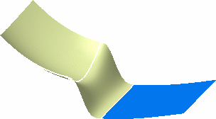
| The final deformed surface looks like this. |
 |
|
 |
Open the
FreeStyle_Part_37.CATPart document. |
 |
-
Select the surfaces to be deformed,
using the Control key for multi-selection.
-
Click the Global Deformation icon:

-
Select the 1 guide option.
-
Click Run in the Global Deformation dialog
box.
-
Select a guiding surface (here the blue surface).
The Control Points dialog box is
displayed.
Use the control points and mesh lines to deform the surface. |
| |
-
Click OK in the Control Points dialog box.
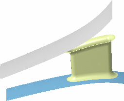
| The deformation is performed along the selected
guide. |
 |
-
Select the 2 guide option.
-
Click Run in the Global Deformation dialog
box.
-
Select two guiding surfaces.
| The Control Points dialog box is
displayed. Use the control points and mesh lines to deform the surface. |
-
Click OK in the Control Points dialog box.
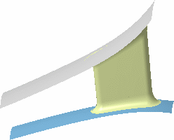
| The deformation is performed along the selected
guide. |
 |
 |
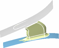
If you check the Continuities on guide
option, the system globally deforms the surfaces while retaining the
continuities on the selected guide.
In our example, the top surface is selected as guide, and the
Continuities on guide is checked. |
|
 |
 |
- When globally deforming re-limited surfaces,
i.e. surfaces which limits have been redefined, make sure that you check
the continuities between faces. Indeed, depending on the geometrical
configuration, it may happen that the set continuities are lost when
deforming.
- Available capabilities from the dashboard are:
auto
detection, attenuation, continuity, orders, and keep original.
|
|
|
![]()