This task explains how to modify a curve using its control points.
Open the FreeStyle_01.CATPart document.
-
Select the curve you wish to edit.

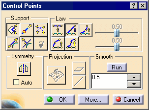
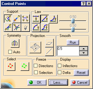
The Control Points dialog box appears.
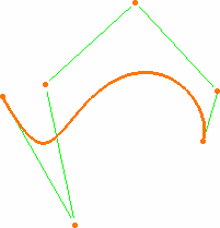
Control points and lines are displayed, along with the 3D compass and the curve degree.
-
If you select a curve that has been created outside the FreeStyle workbench, and the curve is not a NUPBS curve (Non-Uniform Polynomial B-Spline), the Converter Wizard will be automatically displayed when the curve cannot be exactly converted, see Approximating/Segmenting Procedural Curves. This allows you to control the conversion tolerance.
However, when a curve can be exactly converted, such as a spline, or line for example, the Converter Wizard is not displayed, the conversion is done automatically and a message is issued. In this case, the Exact text is displayed on the element for information. -
Planes and lines are used to quickly orientate the compass in the control points command. Therefore if you select a plane or a line, it will modify the compass orientation.
-
By default all control points and mesh lines are selected. Click a specific point to deform the surface at this point only, or select a set of points using the Ctrl-key or Shift-key while clicking (multi-selection capabilities). The same applies to mesh lines.
-
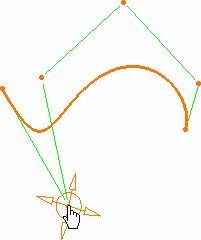
Move the pointer over a point or a line.
Arrows are displayed according to the Support and Law options active in the Control Points dialog box:
-
Support defines the type of translation to be applied
-
Law defines the type of deformation that is to be applied when several control points have been selected.
-
Pull on the arrow matching the direction in which you want to deform the curve.
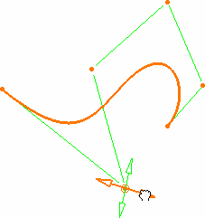
The value is displayed on the curve.
-
Use the contextual menu to choose the order number for the curve.
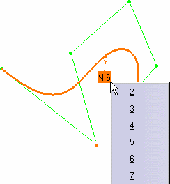
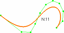
If you increase the order number to 11, the result is:
-
Click OK in the Control Points dialog box to validate the modifications.

Further modification options are available from the More... button of the Control Points dialog box:
-
To perform a quick analysis of the mesh line inflection, select the Inflections option.
-
Freezing of the selected points (no other can be selected) and of the Support option.
-
Dynamic display of the initial curve and of the delta as you pull on the control points.
-
Global selection/de-selection of control points using the Select All
 and De-Select All
 icons, without
having to click the geometry.