- Text with Leader
- Text
- Text parallel to screen
You can set graphic properties (anchor point, text size and justification) either before or after you create the free text.
See Setting Basic Graphical Properties.
You can change any text to another kind at any time.
-
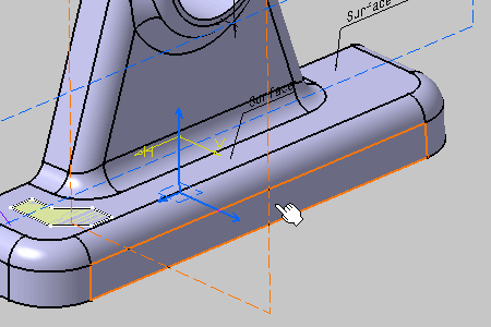
Select the face as shown to define a location for the arrow end of the leader.
The Text Editor dialog box appears. 
- This scenario illustrates the creation of a text by selecting geometry, but you can also select any Part Design or Generative Shape Design feature in the specification tree. In this case, the created annotation will not be attached to the selected feature, but to its geometrical elements at the highest level.
- If the active view is not valid, a message appears informing you that
you cannot use the active view.
This means that the annotation will be displayed in an annotation plane normal to the selected face.
For more information, see View/Annotation Planes.
-
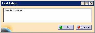
Enter your text, for example "New Annotation" in the dialog box.
-
Click OK to end the text creation. You can click anywhere in the geometry area too.
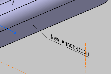
The text appears in the geometry.
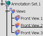
The text (identified as Text.xxx) is added to the specification tree.The leader is associated with the element you selected. If you move either the text or the element, the leader stretches to maintain its association with the element.
Moreover, if you change the element associated with the leader, application keeps the associativity between the element and the leader.
Note that using the Text Properties toolbar, you can define the anchor point, text size and justification.
-
Select the face as shown.

-
Enter your text, for example "New Annotation 2" in the dialog box and click OK.
The text appears in the geometry.
The text (identified as Text.xxx) is added to the specification tree.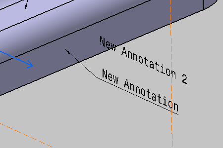
-
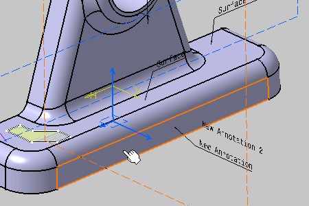
Select the face as shown.
-
Enter your text, for example "New Annotation 3" in the dialog box and click OK.
The text appears in the geometry. 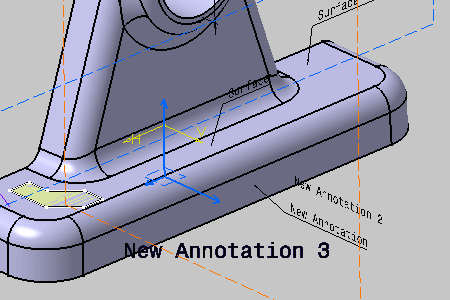
See also Setting Annotation Parallel to Screen. 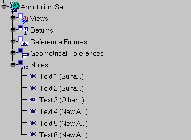
You can move a text using either the drag capability. See Moving Annotations.
Note also that you can resize the manipulators.
For more information, refer to Customizing for 3D Functional Tolerancing & Annotations.