Once you have selected the Display and Hatching, coloring or dotting for clipping plane option:
- When no material is applied to the part, coloring is applied to the clipping plane and the color is the first color returned by the PartBody.
-
When a material is applied to the part, use the Drawing tab
of the material properties to customize the representation of the
clipping plane:
- You can select Hatching, Dotting or Coloring,
- You can set their parameters according to your needs,
- When the same hatching definition is applied to several parts of an assembly, the hatching orientation follows the standard defined by your administrator.
In assembly context:
- When the root product is activated, the same hatching definition
is applied to all the parts involved by the clipping plane:
- For the first part, for which a material is applied, the hatching orientation of the definition is applied .
- For the following parts, for which a material is applied, the hatching orientation angle is retrieved from a list defined in the standard.
- For each part, for which no material is applied, the first color returned by its own PartBody is applied to the clipping plane.
- When a part is edited or a sub-assembly activated:
- Only the part or parts contained in the sub-assembly are clipped according to the Display and Hatching, coloring or dotting for clipping plane option.
- Other parts are clipped with the Low-intensity elements color setting, see Tools > Options > General > Display > Visualization tab.
- Make sure that the Display option under
Hatching, coloring or dotting for clipping plane. is
selected.
Go to the Tools > Options > Mechanical Design > Functional Tolerancing and Annotation > Display tab.
-
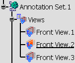
Activate the Front View.2 annotation plane.

-
Click Clipping Plane
 in
the
Visualization
toolbar.
in
the
Visualization
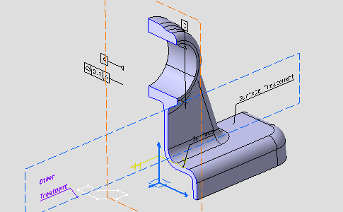
toolbar.The part is clipped according to the annotation plane in relation to its normal. 
This is the default behavior. -
Select PartBody and click Apply Material
 in the Apply Material toolbar,
to apply the metal Aluminium to the part.
-
Right-click Aluminium and select Properties.
-
Select the Drawing tab.
-
Select Hatching in the list if needed and click OK.
-
Unselect and reselect the Clipping Plane
 to refresh the clipping.
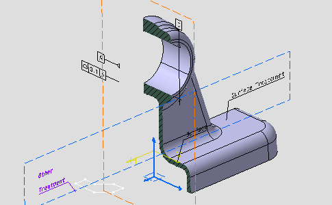
Hatching is displayed. 