![]()
This schema is based on the fact that an object is defined as a class, which one is associated to a behavior set. Thus, an electrical connector corresponds to the Connector class, to which the Connector and Product behaviors are associated.
Electrical Objects
- Harness
- Harness
- Product
- Wire
- Wire
- Product
- Wire group
- Wire group
- Product
- Equipotential
- Equipotential
- Equipment
- Equipment
- Product
- Function
- ConnectorShell
- ConnectorShell
- Product
- Connector
- Connector
- Product
- Splice
- Splice
- Product
- Pin
- Pin
- Product
- Cavity
- Cavity
All these classes derived from the Object abstract class. This one is not to be used as is but allows you to define the Name attribute for all the classes deriving from the Object class.
|
|
The units for all the attributes are given in the standard MKS system. |
The following behaviors, associated to the electrical objects are defined in the iXF electrical schema (behavior named ClassBehavior):
- Harness
- Attribute: SubType
- Wire
- Attributes: InnerDiameter, OuterDiameter (mandatory), BendRadius, Length, Color, LinearMass, SeparationCode, SubType, SignalId
- Wire group
- Attributes: PartNumber, SubType, Color, Diameter, WireLengthCoefficient, BendRadius, SeparationCode, WireGroupLength, ReferenceDesignator
- Equipment
- Attribute: SubType
- ConnectorShell
- Attribute: SubType
- Connector
- Attributes: SubType, Color, MatingConnector
- Splice
- Attribute: SubType
- Pin
- Attribute: SubType
- Cavity
- Attribute: SubType
- Product
- Attribute: PartNumber
- Equipotential
- Attributes: EstimatedDiameter, SeparationCode, RoutingPriority, WirePartNumber, SubType
- Function
- Attributes: System_Type (mandatory if the Function behavior is defined), Description, Localization
At last, all the objects expressed in a iXF document have an attribute identifying in a unique way each object within the project, except for the objects of Link type, which have a unique identifier within the document.
To illustrate how to describe an electrical object with the iXF format, let's take the example of an electrical connector:
This electrical connector of Connector class has:
- As identifier: V242 (attribute 'id')
- As name: Motor,Window_Driver (attribute 'Name')
- As reference: 5584555 -5W (attribute 'PartNumber' via its Product behavior)
- As subtype: Single Insert Connector (attribute 'SubType' via its Connector behavior)
- As color: Yellow (attribute 'Color' via its Connector behavior)
Relations between Electrical Objects
Using a Link type behavior
Nearly all the relations between electrical objects take the form of objects with a Link type behavior.
The Link object classes of the electrical schema are the following:
- WireLink
- WireGroupLink
- EquipotentialLink
- DeviceLink
- HarnessLink
These object classes allow you to define:
-
the connectivity of the wire and equipotential objects, that is to say their connections with the electrical components (instantiated standard parts).
-
The aggregation relations between the electrical components (instantiated standard parts).
For example a connector with pins or an equipment with connectors and pins. -
The harness composition (wires and electrical components)
These links take the form of identifiers.
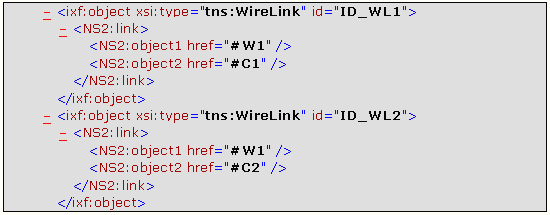
For example: a wire, which identifier is W1, connected to two
electrical connectors, which identifiers are C1 and C2:
Using a Specific Attribute
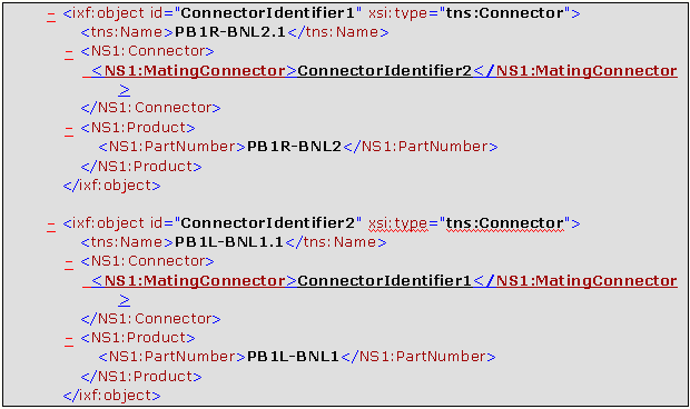
The relation between two connectors (mating connector, connector) is not managed by a Link type object as above but using a specific attribute named MatingConnector (behavior attribute of Connector type). This attribute is optional and is valuated with the identifier of the mating connector on both sides of the connection.
Let see an example where two connectors are connected together. The connectivity between them is described as follows:


