![]()
-
Switch to Electrical Harness Assembly workbench
 .
. -
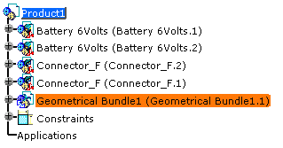
Insert a new product under the root product.
Either use the contextual menu - Components > New Product - or select the Insert > New Product menu item. -
Click Geometrical Bundle
 .
.
-
Switch to Electrical Assembly Design workbench
 again.
 -
Double-click to activate the geometrical bundle to place the extremities.
-
Click Manage Links
 .
.The component list displays: 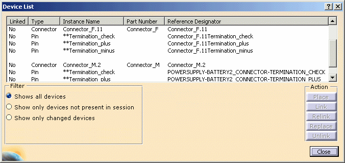
You will place the mating connectors: Connector_M.11 and Connector_M.2. -
Select a connector, for example Connector_M.11
-
Click Place.
Since a mapping has been defined, the catalog browser opens with the predefined connector: 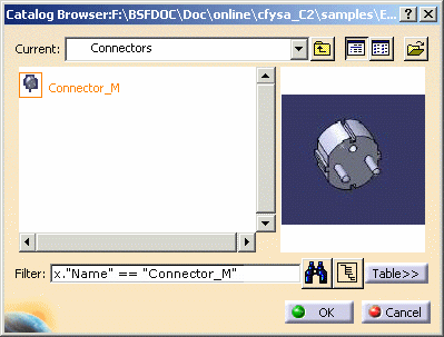
-
Select this connector: Connector_M and click OK.
The connector is placed and automatically linked, together with the pins that belong to it.
They are added to the specification tree under the active product and appear in the geometry at the origin (0, 0). You change the location using the compass.The component list is updated: the connector and pins are shown as Linked in the device list.
-
Repeat these steps for the other mating connector if you perform the whole scenario.
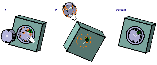
The result looks like this: 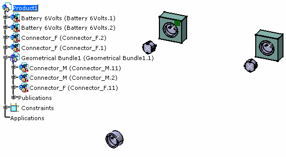
You will now connect the male connectors to the batteries.  The
parent product, common to both devices to be connected, must be
active.
 -
Click Connect Electrical Devices
 .
.Select successively the connector connection point of both connectors to link them. 