For your information, this document references the MemberForDim.CATProduct document. You do not need to open this product.
-
Click Chained Technological Feature Dimensions
 in the Dimensioning toolbar (Technological Feature
Dimensions sub-toolbar).
 You can also click Technological Feature Dimensions
 and then activate Chained Technological Feature Dimensions
 in the Tools Palette.
-
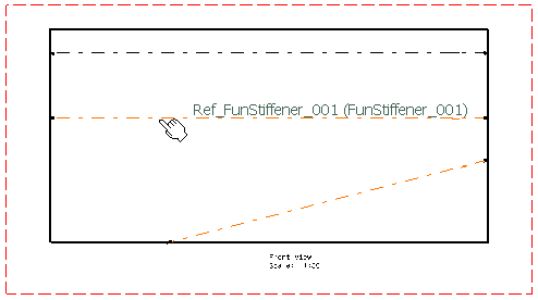
Select Ref_FunStiffener_002 as the first feature for dimensioning. Note that the name of a feature is displayed as a help as you move the cursor over it.
-
Select Ref_FunStiffener_001 as the second feature.

A preview of the dimension is displayed. The dimension creation command remains active.
-
Right-click and select Angle between supports (true dimension).
The next dimension will be created between the previously selected feature (i.e. the second feature you selected) and the next feature you select.
-
Select the third feature.

You can also right-click to view the various types of dimensions you can create between the features. For the purpose of this scenario, leave Distance between parallel supports (true dimension) selected.
-
Optionally move the dimension to position it as wanted.
-
When done, click in the drawing (but not on a technological feature) to create the dimension. The inter-feature dimensions are created as specified by the feature.
You can now handle the dimensions just like any other dimension.

Note that the dimension arrow is automatically oriented according to the direction of material (in this case, the stiffener's molded side), which is the case when dimensioning structural features.
 |
![]()