-
Select the dimension you just created (whatever the type).
-
Select Edit > Properties.
You can also right-click on this dimension and then choose Properties from the contextual menu.
-
In the Properties dialog box that appears, click the Dimension Line tab. The associated dialog box is displayed. Not all fields are active: their activation depends on your choice of options.

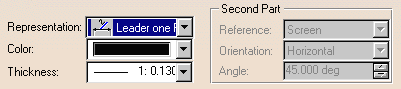
Representation
- Representation
Specify how you want the dimension line represented: Regular, Two Parts, Leader one Part, Leader two Parts.
- Extension
Choose an extension type for your dimension line.
-
Color
Choose a color for the dimension line.
-
Thickness
Specify the thickness for the dimension line.
Leader and Second Part
Leader
Leader Angle: Specify the angle for the first part of a leader one part/two parts.
Leader Length: Specify the length for the first part of a leader two parts.

It is not possible to define a leader length for a leader one part.
Second Part
If you chose Two parts or Leader two Parts for the representation, you need to provide information about the second leader part:
- the Reference for positioning the second part of the dimension line,
- the Orientation for the secondary part of the dimension line in relation to its reference,
- the Angle for the secondary part of the dimension line in relation to its reference (if you selected Dimension Line in the Orientation field and Fixed Angle in the Reference field).
Leader Angle: Specify the angle you want for the extension line.
Symbols
Choose the properties you want to apply to Symbol 1, Symbol 2 (you may need to check this box to specify you want to the dimension to display two symbols), and Leader Symbol (if you chose to represent the dimension line with a leader).
Symbol 1 / Symbol 2 / Leader Symbol
- Shape: you can choose the dimension line shape (open arrow, outlined circle, plus, etc.).
- Color: you can choose the symbols color.
- Thickness: you can define the symbol thickness.
- Reversal: you can set the position of the symbols (inside or outside) in relation to the extension line.
In the case of two-symbols dimensions, you can specify a different position for each symbol (i.e. symbol 1 inside and symbol 2 outside, or vice-versa).
You can also do this interactively using the Ctrl key.
Foreshortened
For radius dimensions, you can activate the Foreshortened option.
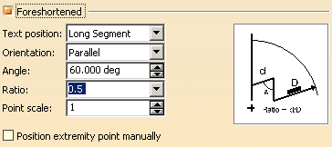 |
- Text position: specify whether the text should be positioned on the long segment or on the short segment of the dimension.
- Orientation: define the orientation of the text associated to the dimension line (parallel or convergent).
- Angle: specify the angle value (must be valued between 180deg and -180deg). The default angle is 60 degrees.
- Ratio: specify the ratio for the short segment and the long segment of the foreshortened dimension.
- Point scale: specify the point scale value.
- Unfix extremity position: check this box to unfix the extremity point of the foreshortened dimension line. You will then be able to move the extremity point using a yellow manipulator.
-
Modify the available options as required.
For example, from the Representation drop-down list, choose Leader two Parts.
-
In the Leader area, specify the angle and the length you want between the two parts of the leader.
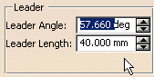
These angle and length are applied to the first segment:

|
|
On a leader one part/two parts, you can also modify these angle and length in the view by dragging the Move dimension leader manipulator
|
You can also drive the second segment from the options in the Second Part area: it can be horizontal, vertical, parallel, perpendicular, fixed angle with screen, view, or dimension horizontal and vertical.
-
Change the Leader symbol in Symbols > Leader Symbol > Shape.
Choose Double Filled Arrow, for example.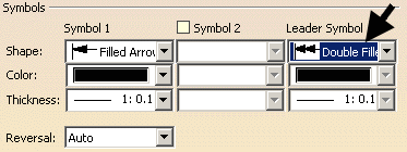
Transform this two parts leader into a one part leader: from the Representation drop-down list, choose Leader one Part.
Click OK to validate and exit the dialog box.
![]()