Dimensions along a reference direction can be created for length, distance, diameter tangent, radius tangent, and overall curve dimensions, as well as on linear (i.e. not angular) cumulated or stacked dimensions.
-
Click Dimension
 in the Dimensioning toolbar.
 -
In the Tools Palette, click Intersection Point Detection
 . Refer
to Creating dimensions between intersection
points for more information about this functionality.
 -
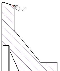
Click the first element, in this case, an intersection point.

-
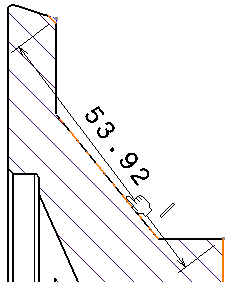
Click the second element.

The dimension to be created is previewed.
-
In the Tools Palette, click Force dimension along a direction
 .
.Several options are then displayed in the Tools Palette:
-
 Dimension along a direction creates the dimension using a
linear element (line, axis line, center line) as the reference
direction, or using an angle to define the reference direction
relatively to a linear element. In the latter case, key in a value in
the Angle field.
 -
 Dimension perpendicular to a direction creates the dimension
perpendicularly to a linear element.
 -
 Dimension along a fixed angle in view creates the dimension
using a fixed angle in the view. In this case, key in a value in the
Angle field.
 Note that such a dimension follows the view rotation. Thus, a dimension line with a 30 deg angle in a view which is set at 45 deg (relatively to the sheet) will be equivalent to a dimension line with a 75 deg angle relatively to the sheet.

These options are also available in the contextual menu that you can display during the dimension creation.
-
-
Click Dimension along a direction
 .
For the purpose of this scenario, leave the Angle field set to
0 deg.
 -
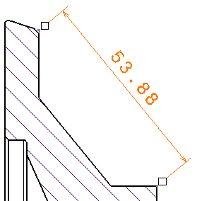
Select a linear element to use as the reference direction. Once created, the dimension will be associative to this element.

The dimension is updated so as to measure the distance between the selected points once projected onto the reference direction.
-
Drag the mouse to position the dimension as wanted.
-
Click to validate the dimension creation.

More About Dimensions Along a Reference Direction
- In the case of a dimension along or perpendicular to a direction, if you delete the linear element used as the reference direction, the dimension will be automatically converted into a dimension along a fixed angle in view (the angle being that of the reference element in the view before its deletion).
-
The behavior of a dimension along or perpendicular to a direction will actually depend on whether the Only create non-associative dimensions option is activated in Tools > Options > Mechanical Design > Drafting > Dimension tab, Associativity on 3D button:
- If it is activated, then the dimension will actually be a dimension along a fixed angle in the view (the angle being that of the reference element in the view).
- If it is not activated, then the dimension will always match the direction of the element defining the reference direction.
- Once a dimension along a reference direction has been created, you cannot modify the elements that define the direction of measure, i.e. either the linear element used as the reference direction or the fixed angle in view.
- The reference direction will not be taken into account when re-routing dimensions (Re-route Dimension command).
- Dimensions along a reference direction cannot be driving dimensions. So, if the Create driving dimension option is activated in Tools > Options > Mechanical Design > Drafting > Dimension tab, you will not be able to drive dimensions when dimensioning along a direction.
- Dimensions created in a shot (i.e. cumulated/stacked dimensions, or dimensions sharing the same type as the first one) all have the same reference direction.
![]()