Applying a Scene to an Assembly

This task consists in snapping components in scene context. 
Insert  the following sample model files in the samples folder:

ATOMIZER
BODY1
BODY2
LOCK
NOZZLE1
NOZZLE2
REGULATOR
TRIGGER
VALVE
REGULATION_COMMAND

1.  Make sure you work in Design mode (Select Poduct.1 and use Edit->Representations->Design Mode menu) 

Click the Create Scene icon I_ScreenReferenceP2.gif (247 bytes).

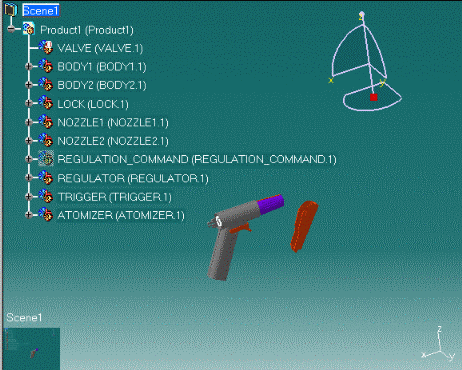
The Edit Scene dialog box and a scene representation in the document window are displayed.
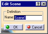
2.  Click Ok to end the scene creation.
3.  Right-click VALVE (VALVE.1)in the specification tree.
4. Select Representations->Deactivate Node from the contextual menu displayed.
5. Right-click NOZZLE1 (NOZZLE1.1) in the geometry area and change the color using the Properties item from the contextual menu displayed.
6. Hide REGULATION_COMMAND (REGULATION_COMMAND.1) using the Hide/show icon from the View toolbar.
7. Move TRIGGER (TRIGGER.1) using the 3D compass.
8. Click the Exit From Scene icon I_CloseP2.gif (214 bytes) to swap to the initial window.
9. Right-click Scene.1 in the geometry area and select Scene.1object ->Apply scene on Assembly.


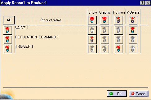
The Apply Scene.1 to Assembly dialog box is displayed.
10. Click All if you want all your modifications to be taken into account and applied on the assembly.

Note: you can select the required modification by clicking the red symbol (swaps to green).
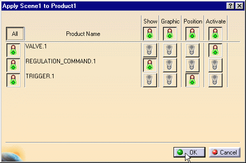
11. Click Ok if you are satisfied with your selection.
Your assembly reflects the scene created. All your modifications performed ( Graphic Properties, Position, show/Hide..) are taken into account.