- The Smart Move combines simple snap and double snap, see the Assembly Snaps reference to know more about the simple snap and double snap capabilities.
- Rules which apply a simple snap or a double snap in Smart Move
are the following:
- The first time you launch the Smart Move or each time that you are selecting a first component different than the first in the previous Smart Move, a double snap is made.
- Each time that you are selecting the same first component as the first in the previous Smart Move, a simple snap is made.
- Run the Smart Move and select the geometrical elements display the simple smart move, otherwise select the affected components and run the Smart Move display the smart move with viewer, compare with Smart Move with Viewer.
- The Smart Move is able to work in visualization mode, which means the positioned component and the positioning parts are no longer needed to be switched into design mode. However, in order to create constraints, you must be working in Design mode.
- The Smart Move is disabled when the Automatic switch to Design mode is off and related components of the Active component in Visualization mode.
-
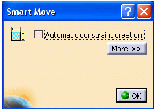
Click on the More button. The Quick Constraint details appear.
The Quick Constraint frame contains the list of the constraints that can be set. This list displays these constraints in a hierarchical order and can be edited by using both arrows to right of the dialog box.

-
Check the Automatic constraint creation option.
The application creates the first possible constraint as specified in the list of constraints having priority. For more about this list, please refer to Quick Constraint.
For automatic constraint creation, the only difference from behavior of Quick Constraint is that simple shapes like point, plane, line and axis system are only considered for this command. Although, the user can select the cylinder, cone and Sphere (using Other Selection from contextual menu), internally these are treated as the simple shapes.
-
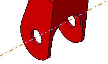
Select the axis of CRIC_BRANCH_1 as shown:

-
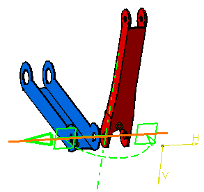
Select the axis of CRIC_BRANCH_3.
Instead of explicitly selecting both axes, you can select the axis of CRIC_BRANCH_1 and then drop it onto the blue inner cylinder face when your cursor points to this face.
The application detects a possible constraint between the axes. As the option Create constraint is on, the application can set a coincidence constraint between both axes.

-
Click the green arrow to reverse the direction of the component.

-
Click OK to confirm and quit the command.
The coincidence constraint is created.
