Editing Constraints 

This task explains you about to edit constraints.
When you are editing a constraint, you can:
  • Rename the constraint.
  • Change the referenced geometries.
  • Modify its options.
  The Copy/Cut/Paste commands are available for valuated constraints only. In this case, only the constraint's value, for the same type of constraint offset or angle, can be pasted. Concerning the Cut command, it deletes the constraint and copy its value.
Open the Assembly_01.CATProduct document.
  1. Double-click the Surface contact.3 constraint.


The Constraint Definition dialog box appears.


  1. Click the More>> button to expand the dialog box.


The traffic lights displays the constraint status:

  • verified.

  • impossible.

  • not updated.

  • broken.


Two contextual commands improving display are available in the Supporting Elements field:

  • Reframe on views the constraint of the selected component at the center of the geometry window.

  • Center Graph zooms in the selected component in the specification tree.


Constraints and Object in Work

  When you are setting constraints and designing part in the assembly at the same time, it is possible that you are modifying the referenced geometries of the constraints. In other words, the geometry of the current feature does not contain the original geometry referenced by the constraint. In fact, the constraint references the original geometry which already exists in the history but not for the current object in work.
In this case, the application cannot highlighted the geometry or the constraint seems to be wrong.
This can happen for Sheet Metal Design features or when you add a transformation feature in Part Design context for example after the constraint's creation.
 
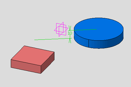
  The body or the brick-red part has been translated using the translate transformation feature of Part Design, note that its magenta axis system has not been moved. The constraint is already verified although one of its referenced geometry has been moved.