 |
 |
-
Open the
Enginehead.CATPart file.
-
From the Tools->Options menu, access
the Infrastructure->Collaboration Infrastructure
category.
-
In the Network tab, check the
Client/Server Mode to specify the selected communication
mode and enter the connection settings in the Connectivity
tab.
-
In the Collaboration Server Connect dialog box,
enter your name, password and role. Click OK when
done.
-
Click the Workspaces icon ( ). ).
-
Click the New button in the Workspaces
dialog box to create a new workspace. Fill in the fields (see
below).
-
Select the workspace you have just created and
click the Join button to join it. The workspace status
turns to Active. Click Close when done.
|
 |
-
From the Tools->Options menu, access
the Infrastructure->Collaboration Infrastructure
category.
-
In the Network tab, check the
Client/Server Mode to specify the selected communication
mode and enter the connection settings in the Connectivity
tab.
-
In the Collaboration Server Connect dialog box,
enter your name, password and role. Click OK when
done.
-
Click the Workspaces icon ( ). ).
-
Select the Engine Head workspace and click the
Join button. Click Close when done.
|
 |
-
From the Start->Mechanical Design
menu, access the Functional Molded Part workbench.
-
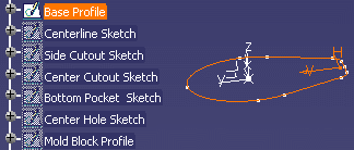
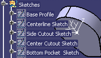
In the specification tree, right-click the Base
Profile located below the Sketches node and select the
Hide/Show command. The following sketch displays:
-
Click the Shellable Feature icon ( )
and click the Base Profile sketch. The Shellable Feature dialog
box displays: )
and click the Base Profile sketch. The Shellable Feature dialog
box displays:
-
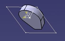
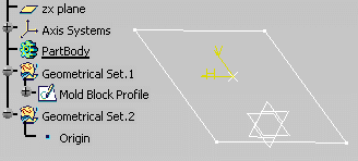
In the specification tree, right-click the Mold
Block Profile located below the Sketches node and select the
Hide/Show command. The following image displays:
-
Select the Mold Block Profile and click the
Share Selected Entities icon ( )
in the Instant Collaboration toolbar. The Briefcase window opens. )
in the Instant Collaboration toolbar. The Briefcase window opens.
|
| |
-
In the specification tree, right-click the Top
Cut Surface located bottom of the Sketches node and select the
Hide/Show command. The surface displays.
-
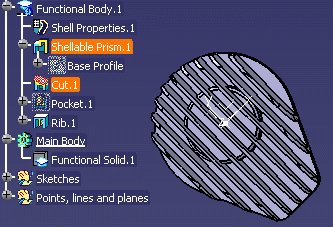
Click the Cut icon ( ):
The Cut window displays. ):
The Cut window displays.
-
Right-click the Top Cut Surface in the geometry
and select the Hide/Show command to hide it.
-
Right-click the Mold Block Profile and select the
Hide/Show command to hide it.
-
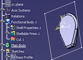
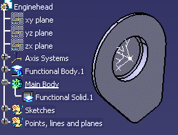
Click the Main Body
from the specification
tree and click the
Share Selected Entities icon ( )
in the Instant Collaboration toolbar. The Briefcase window opens.
Enter the subject of the briefcase: Main body and click OK.
The briefcase is sent. )
in the Instant Collaboration toolbar. The Briefcase window opens.
Enter the subject of the briefcase: Main body and click OK.
The briefcase is sent.
|
 |
-
From the Start->Mechanical Design
menu, access the Functional Molded Part workbench and
create a New Part.
-
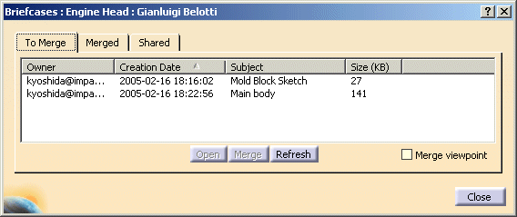
Click the Briefcases open/close icon ( )
to list the existing briefcases. The ones you received display in
the To Merge tab. )
to list the existing briefcases. The ones you received display in
the To Merge tab.
-
Click the Mold Block Sketch and click the
Merge button. After you merged it, you would notice the
entity you just merged disappeared and moved in Merged tab.
-
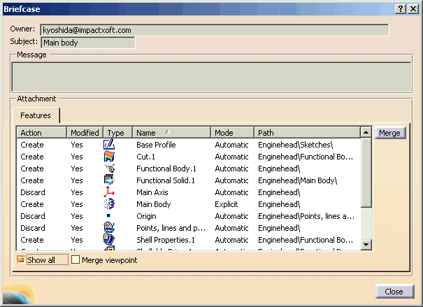
Select the Main Body and click Open
button. Briefcase window appears. Check Show all check box to
see which entities you are receiving.
-
Click the Merge
button.
-
Select Body.1 in the specification tree and rename it to Mold Block.
-
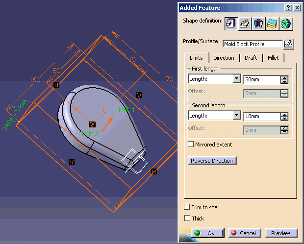
In the External Volume toolbar, click the
Added Feature icon ( ).
The Added Feature dialog box displays: ).
The Added Feature dialog box displays:
-
Right-click the Mold Block and select the
Hide/Show command.
|
 |
-
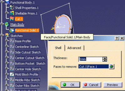
Double-click the Shell Properties.1 located below
the Functional Body.1 in the specification tree. The Shell
Properties dialog box displays.
|
|
|
|
|
 |
-
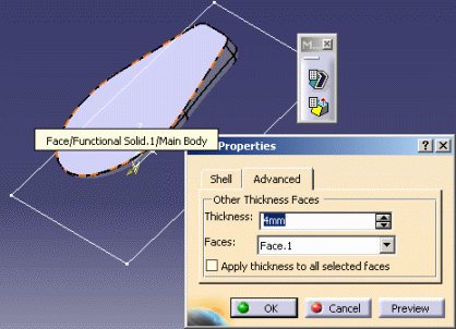
In the Advanced tab, change the thickness
to 4mm, select Face.1 of Main Body for Faces, and click OK
when done.
|
|
 |
-
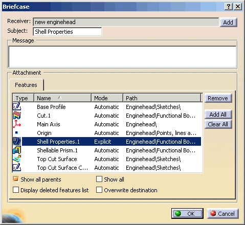
Click the Shell Properties in the geometry and
click the Share Selected Entities icon ( )
in the Instant Collaboration toolbar. The Briefcase window
opens. Enter the subject of the briefcase: Shell Properties.
Check Show
all parents checkbox to see what other entities will be sent
along with Shell Properties. Click OK. The briefcase is sent. )
in the Instant Collaboration toolbar. The Briefcase window
opens. Enter the subject of the briefcase: Shell Properties.
Check Show
all parents checkbox to see what other entities will be sent
along with Shell Properties. Click OK. The briefcase is sent.
 |
| |
-
In the specification tree, right-click the Bottom
Pocket Sketch located below the Sketches node and select the
Hide/Show command.
-
Click the Pocket icon ( )
and select the Bottom Pocket Sketch in the geometry. The Pocket
window displays. )
and select the Bottom Pocket Sketch in the geometry. The Pocket
window displays.
-
Click the Pocket in the geometry and click the
Share Selected Entities icon ( )
in the Instant Collaboration toolbar. The Briefcase window opens.
Enter the subject of the briefcase: Pocket and click OK.
The briefcase is sent. )
in the Instant Collaboration toolbar. The Briefcase window opens.
Enter the subject of the briefcase: Pocket and click OK.
The briefcase is sent.
|
 |
-
Click the Briefcases open/close icon ( )
to list the existing briefcases. The ones you received display in
the To Merge tab. )
to list the existing briefcases. The ones you received display in
the To Merge tab.
-
Select Shell Properties briefcase and click the
Merge button.
-
Select Pocket briefcase and click the Merge
button.
-
From the Start->Shape menu, access the
Generative Shape Design workbench.
-
Zoom in to enlarge your part.
-
Right-click the Sketches node and select the
Define In Work Object command.
-
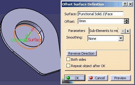
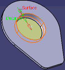
Select the Functional Solid.1\Face (see graphic
below) and click the Offset icon
( ). The
Offset Surface Definition window displays. Click OK to
close the dialog box. ). The
Offset Surface Definition window displays. Click OK to
close the dialog box.
-
Select the Functional Solid.1\Face\Main Body and
click the Offset icon ( ).
The Offset Surface Definition window displays. Click OK
to close the dialog box. ).
The Offset Surface Definition window displays. Click OK
to close the dialog box.
-
Select the other Functional Solid.1\Face\Main
Body and click the Offset icon ( ).
The Offset Surface Definition window displays. Click OK
to close the dialog box. ).
The Offset Surface Definition window displays. Click OK
to close the dialog box.
-
Click the Join icon ( ).
The Join Definition dialog box displays. ).
The Join Definition dialog box displays.
-
In the specification tree, right-click the Mold
Block Profile (below the Geometrical Set.2 node) and select the
Hide/Show command. The profile displays.
-
Click the Mold Block Profile in the geometry and
click the Fill icon (
 ).
The Fill Surface Definition dialog box displays. Click OK
when done. ).
The Fill Surface Definition dialog box displays. Click OK
when done.
-
Right-click the Main Body in the specification
tree and select the Hide\Show command.
-
Zoom out, right-click the Mold Block Profile and
select the Hide\Show command.
-
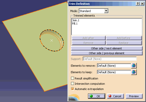
Click the Trim icon ( ).
The Trim Definition dialog box displays: ).
The Trim Definition dialog box displays:
-
From the Start->Mechanical Design
menu, access the Functional Molded Part workbench.
-
Right-click the Mold Block body in the
specification tree and select the Hide/Show command.
The body displays.
-
Right-click the Mold Block body in the
specification tree and select the Define in Work Object
command.
-
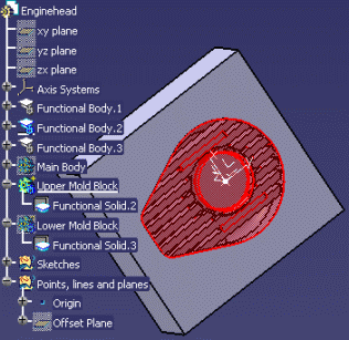
Click the Divide icon ( ),
the Divide dialog box displays: ),
the Divide dialog box displays:
-
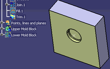
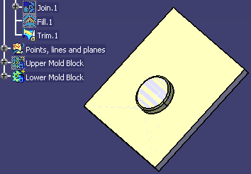
After the Divide, Divide Body.2 and Divide Body.3
were created. Rename them to Upper Mold Block and Lower Mold
Block.
-
Right-click the Mold Block in the
specification tree and select the Hide/Show command to
hide.
-
Right-click the Lower Mold Block in the
specification tree and select the
Hide/Show command to hide.
-
Right-click the Upper Mold Block in the
specification tree and select the
Hide/Show command to hide. And right-click the Lower
Mold Block in the specification tree and select the Hide/Show
command to display.
-
Right-click the Lower Mold Block in the
specification tree, and select the
Hide/Show command.
-
Select the Main Body and select the
Hide/Show command. The Main Body displays.
|
 |
-
In the specification tree, right-click the Middle
Ribs Sketch located below the Sketches node and select the
Hide/Show command. The Ribs sketch displays.
-
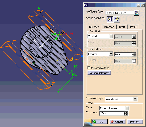
Click the Rib ( )
icon and select the Ribs in the geometry. The Rib dialog box
displays: )
icon and select the Ribs in the geometry. The Rib dialog box
displays:
|
-
In the specification tree, right-click the Outer
Ribs Sketch located below the Sketches node and select the
Hide/Show command. The Outer Ribs sketch displays.
-
Click the Rib ( )
icon and select the outer ribs in the geometry. The Rib dialog
box displays: )
icon and select the outer ribs in the geometry. The Rib dialog
box displays:
-
Click the Share Selected Entities icon ( )
in the Instant Collaboration toolbar and select Rib.1 and Rib.2
in the specification tree. The Briefcase window opens. Enter the
subject of the briefcase: Ribs and click OK. The
briefcase is sent. )
in the Instant Collaboration toolbar and select Rib.1 and Rib.2
in the specification tree. The Briefcase window opens. Enter the
subject of the briefcase: Ribs and click OK. The
briefcase is sent.
-
In the specification tree, right-click the Center
Hole Sketch located below the Sketches node and select the
Hide/Show command. The Center Hole sketch displays.
-
Click the Cutout ( )
icon: the Cutout window displays. Select the Center Hole Sketch
in the geometry. )
icon: the Cutout window displays. Select the Center Hole Sketch
in the geometry.
-
Click the Cutout you have just created in the
specification tree and click the Share Selected Entities icon ( )
in the Instant Collaboration toolbar. The Briefcase window opens.
Enter the subject of the briefcase: Center Hole and click OK.
The briefcase is sent. )
in the Instant Collaboration toolbar. The Briefcase window opens.
Enter the subject of the briefcase: Center Hole and click OK.
The briefcase is sent.
|
| |
-
In the specification tree, right-click the Side
Cutout Sketch and the Center Cutout Sketch located below the
Sketches node and select the Hide/Show command. The sketches
display.
-
Click the Cutout ( )
icon: the Cutout window displays. Select the Center Cutout Sketch
in the geometry. )
icon: the Cutout window displays. Select the Center Cutout Sketch
in the geometry.
-
Click the Cutout ( )
icon: the Cutout window displays. Select the Side Cutout Sketch
in the geometry. )
icon: the Cutout window displays. Select the Side Cutout Sketch
in the geometry.
-
Click the two Cutouts you have just created in the
specification tree and click the Share Selected Entities icon ( )
in the Instant Collaboration toolbar. The Briefcase window opens.
Enter the subject of the briefcase: Center-Side Cutouts and click OK.
The briefcase is sent. )
in the Instant Collaboration toolbar. The Briefcase window opens.
Enter the subject of the briefcase: Center-Side Cutouts and click OK.
The briefcase is sent.
-
In the specification tree, right-click the Bolt
Hole Sketch located below the Sketches node and select the
Hide/Show command. The Bolt Hole Sketch displays.
-
Click the Cutout ( )
icon: the Cutout window displays. Select the Bolt Hole Sketch
in the geometry. )
icon: the Cutout window displays. Select the Bolt Hole Sketch
in the geometry.
-
Click the Cutout you have just created (CutOut.4)
in the specification tree and click the Share Selected Entities icon ( )
in the Instant Collaboration toolbar. The Briefcase window opens.
Enter the subject of the briefcase: Bolt Holes and click OK.
The briefcase is sent. You are done with the design. Click
here to display
the result sample part. )
in the Instant Collaboration toolbar. The Briefcase window opens.
Enter the subject of the briefcase: Bolt Holes and click OK.
The briefcase is sent. You are done with the design. Click
here to display
the result sample part.
|
 |
-
Click the Briefcases open/close icon ( )
to list the existing briefcases. The ones you received display in
the To Merge tab. )
to list the existing briefcases. The ones you received display in
the To Merge tab.
-
Click the Ribs briefcase and click the Merge
button.
-
Click the Center Hole briefcase and click the
Merge button.
-
Click the Center-Side Cutouts briefcase and click the
Merge button.
-
Click the Bolt Hole briefcase and click the
Merge button.
-
Expand the Functional Body.1 node and right-click
Cutout.4 feature, select the Cutout.4 object-> Deactivate
command.
-
Right-click Cutout.1 feature, select the
Cutout.1 object-> Deactivate command.
-
Select the Lower Mold Block in the specification
tree, and select the Hide/Show command to display.
-
Click the Fitting icon ( ),
the Fitting dialog box displays: ),
the Fitting dialog box displays:
-
Right-click the Upper Mold Block and select the
Define in Work Object command.
-
Right-click the Lower Mold Block and select the
Hide/Show command.
-
Right-click the Main Body and select the
Hide/Show command.
-
Click the Fitting icon ( ),
the Fitting dialog box displays: ),
the Fitting dialog box displays:
-
Right-click the Upper Mold Block and select the
Hide/Show command (see graphic below). Hide it again.
-
Right-click the Lower Mold Block and select the
Hide/Show command. The Lower Mold block displays.
Click here to
display the result sample file.
|
|

