The constraint areas belong to the board part in separate bodies.
![]()
-
Choose the Insert > Body menu item.
-
Double-click to activate the newly created body.
-
Select the board to define the working plane.
-
Click Profile
 and draw the following contour:
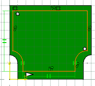
-
Enter 1mm for Length.
-
Click OK to validate.
-
The Constraint Areas dialog box opens. 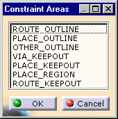
-
Choose PLACE_OUTLINE and click OK.
The PLACE_OUTLINE area is displayed in transparency.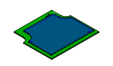
-
Repeat steps 1 to 10 to create another constraint area on the other face of the board according to the following contour:
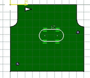
-
Select Constraint Area
 .
.
The Constraint Areas dialog box opens. -
Choose PLACE_KEEPOUT and click OK.
The PLACE_KEEPOUT area is displayed in transparency.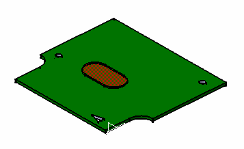
The pads are more than simple pads: they have technological properties.
An alternative: the steps 10 and 11 can take place before step 3.